Landoll 5211 Grain Drill User Manual
Page 28
3-6
F-725-1213 Edition
ASSEMBLY INSTRUCTIONS
8.
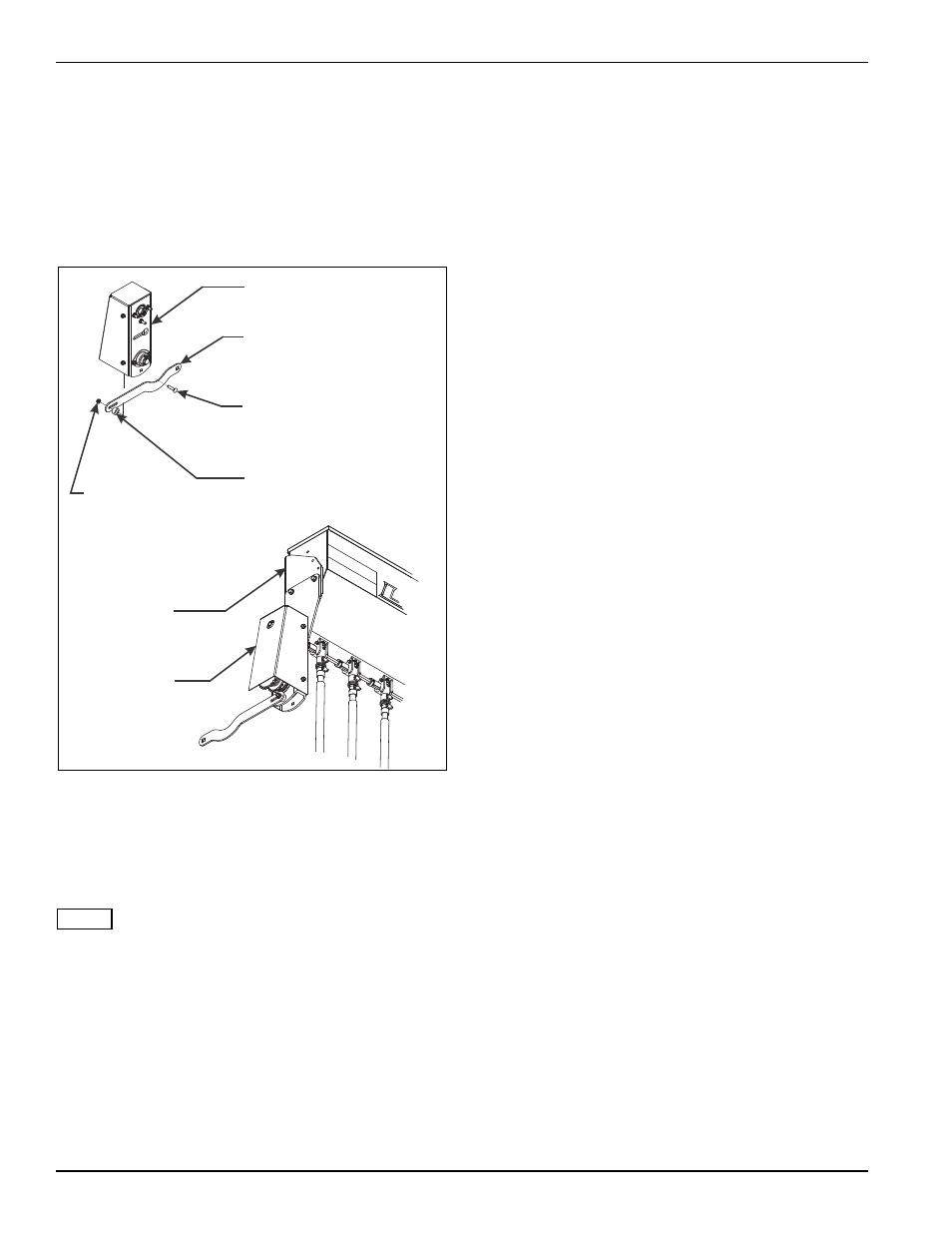
Attach the front of the chain adjustment bracket to
the seed box bracket with the 1/2-13 x 1-1/4 hex
head cap screw.
9.
Attach the slotted rear hole of the chain adjustment
bracket to the outer hole of the small seed bearing
assembly with a 5/16-18 x 1-1/2 round head square
neck screw, 1” OD spacer and hex flange nut (See
Figure 3-4.)
Figure 3-4: Attaching Chain Adjustment Bracket to
Small Seed Bearing Assembly
10. Remove rear walkboard and right and left mounting
brackets. Using existing screws, install new
extended walkboard mounts to the rear of the drill
frame. Reattach walkboard to new extended mounts.
NOTE
For 10 & 12-1/2 drills – If the drill has the optional dry
fertilizer attachment, the grass seed bracket and bearing
will not be used, go to step 12.
For 15’ & 20’ drills –If the drill is a 3PT model, the grass
seed bracket and bearing will not be used, go to step 12.
11. Remove existing 7/8 hex drive shaft above the drill 7
x 7 frame tube. Install the grass seed bracket and
bearing to the rear of the main drill 7 x 7 frame. See
page 2-16 for proper placement. Reinstall the hex
drive shaft, see placement dimensions.
12. Install the 24 tooth drive sprocket and locking set
screw on the end of the hex drive shaft (See page
2-16 for proper placement.)
13. Remove the rear safety shield from the seed shaft
bearing assembly. Loosen the rear mounting
screws, then lift up and remove the shield and
screws.
14. Install the connecting link in the roller chain, and
install between the front 24 tooth drive sprocket and
outer bearing on the seed shaft bearing assembly.
Loosen the 5/16-18 flange head serrated nut through
the chain adjustment bracket. Pull the lower end of
the seed shaft bearing assembly rearward to tighten
the drive chain. Retighten the 5/16-18 flange head
serrated nut and the three hex lock nuts that attach
the seed shaft bearing assembly to the mount on the
end of the small seed box. Verify drive chain
alignment, and adjust front 24 tooth sprocket if
necessary.
15. Reinstall the safety shield over the seed shaft
bearing assembly.
16. For 15’ & 20” drills – Screw the threaded coupler
drive into the open end of the seed shaft bearing
assembly. Slide the square end of the drive tube over
the square seed shaft of the left small seed box.
Connect the drive tube and threaded coupler drive
with the 6” shaft coupler using 1/4-20 x 1-3/4 hex
head cap screws and hex lock nuts.
17. Install the metal small seed tubes in the mounting
holes in each drill opener frame using 1/4-20 x 1
round head square neck screws and nuts. Note the
lower end of the small seed tube points rearward
towards the press wheels. The seed tube has two
sets of mounting holes. Initially slide the seed tube
forward. The tube may be positioned farther back for
shallower planting depth if desired.
18. Attach the telescoping seed tube assemblies to the
small seed box and small seed tubes on the opener.
The larger OD telescoping seed tube attaches to the
opener, while the smaller tube attaches to the small
seed box.
19. ,Attach the SMV sign to the SMV mounting bracket
with 1/4-20 x 3/4 hex head cap screws and hex lock
nuts. Using 1/4-20 x 1-1/4 hex head cap screws and
hex lock nuts, attach the SMV and bracket to the
seed box mounting bracket extending below the
small seed boxes in the center of the machine. For
15’ & 20’ drills, install the seed shaft shield under the
SMV mounting bracket.
small-seed1
SEED SHAFT BEARING
ASSEMBLY
CHAIN ADJUSTMENT
BRACKET
5/16-18 X 1-1/2 RD HEAD
SQ NECK SCREW
SPACER
5/16-18
FLANGE HEAD
SERRATED NUT
SMALL SEED BOX
ASSEMBLY
SEED SHAFT
BEARING
ASSEMBLY