Landoll XL144/XLC144/XLD144/XLH144/XLO144 X-Fold Pulverizer User Manual
Page 28
5J801
182rev501
Page 17
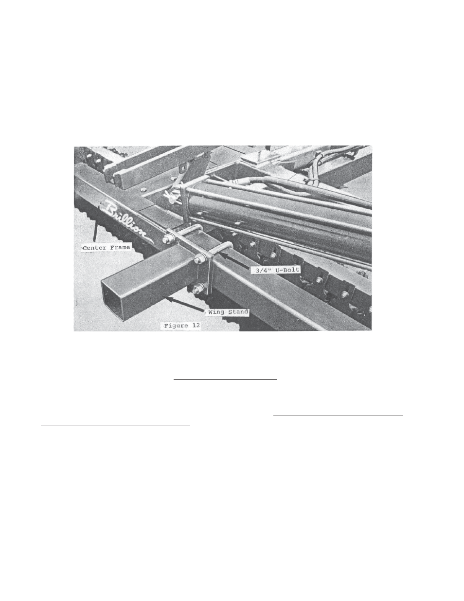
26' MODELS LEFT WING STAND See Figure 12
Attach the wing stand on the rear side of rear tube on the center frame with the U-bolts, lockwashers and nuts
that are with the wing stand. Position the wing stand between the two 2" x 4" rectangular tubes next to each
other. Slide the wing stand to the left as far as possible. After wings are folded the stand may be moved right
slightly to match the wing.
HYDRAULIC LINE ASSEMBLY
(See Figures 11 and 13)
Assemble the four flow restrictors into ports on wing folding cylinders. Note the steel tubing as shown in some
pictures has been replaced by hydraulic hose.
Install the optional 6J-194 manual valve kit if used next to the rod end flow restrictors in the wing fold cylinders.
Telescope drawbar to the lengthened position and lock in place with a 1" x 9-1/4" long pin. Attach the two long
angles to the top center of the drawbar with two 1/2 x 2" long capscrews, lockwashers and nuts. Next attach
the “L” clamps to the drawbar with 5/16" x 1" long capscrews and lockwashers.
Connect the hoses and fitting as shown. Attach hoses to the drawbar “L” clamps and long angles with
5/16" x 1" long capscrews, lockwashers and nuts.
Use the short hose tie to fasten the two right wing fold cylinder hoses together over the center frame. Use one
long hose tie to fasten these two hoses to the front 4" x 4" cross tube on the center frame to keep hose from
being above 2" x 4" frame tube. On some models left wing stand will rest on this tube.