Landoll XL144/XLC144/XLD144/XLH144/XLO144 X-Fold Pulverizer User Manual
Page 17
5J801
182rev501
Page 9B
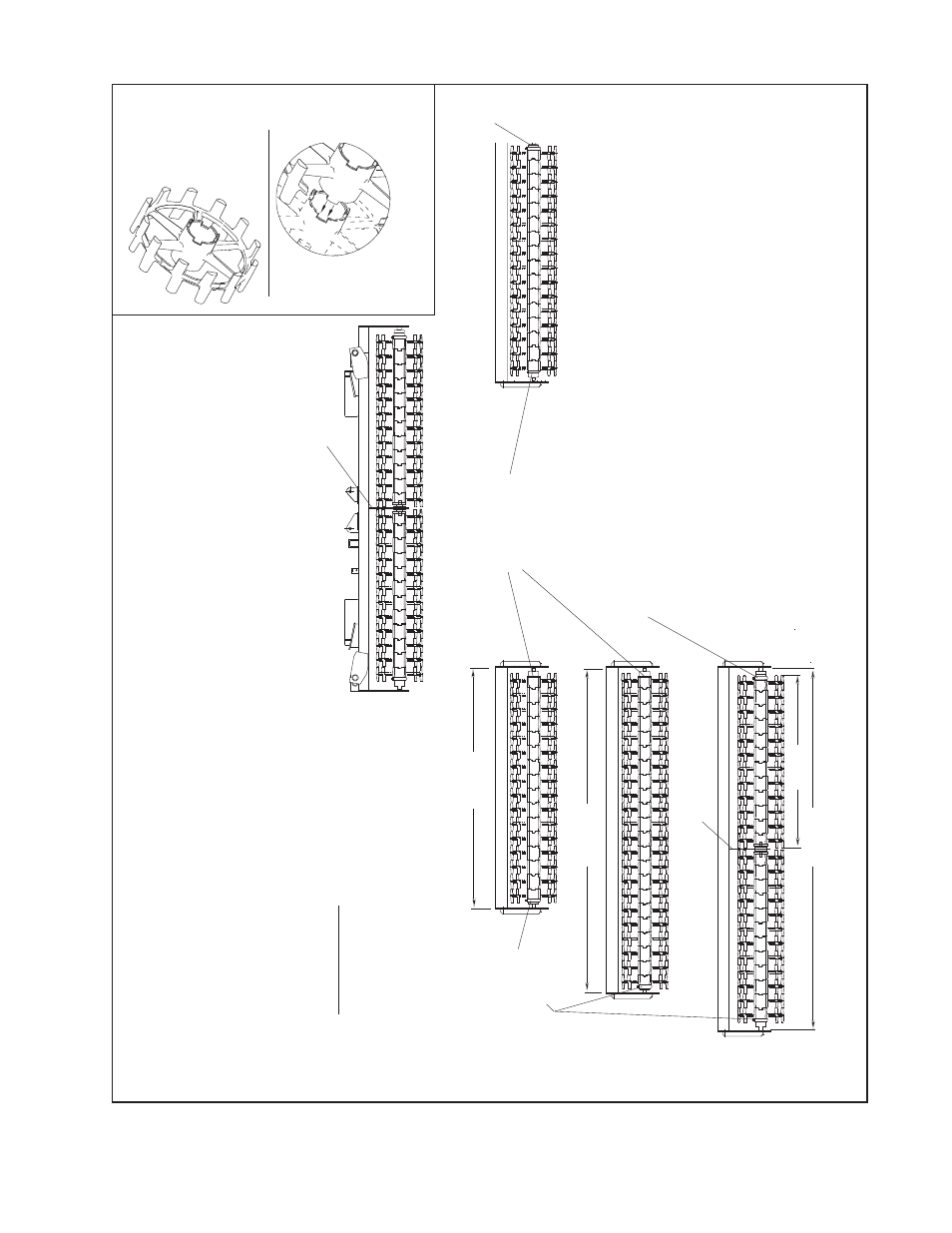
OPTIMIZER
WHEEL
PLACEMENT
28’
- 36’
Wide
Models
with
20”
Optimizer
Wheels
-
4
1/2”
bore
(6K353
Wheel
&
6K354
End
Wheel)
“XLO”
Models
CENTER SECTION
(2x)10
Wheels,
(2x)2
End
Wheels)
WING ASSEMBL
Y
/ side:
8’=14
Wheels,
2
End
Wheels
9’=16
Wheels,
2
End
Wheels
10’=18
Wheels,
2
End
Wheels
11’=20
Wheels,
2
End
Wheels
12’=(2x)10
Wheels,
(2x)2
End
Wheels
Position Welded
Ring
on
Axle
to
inside
Male
&
female ends must mate and remain in close contact.
8’
Wing
Position Axle
Clamp
to
outside
Position Axle
Clamp
to
outside
11
’ W
in
g
The
above
diagram
shows
wheel
gang
positioning
and
assembly
for
the
center
and
wings
of
optimizer
model
pulverizers
using
optimizer
wheels.
When
assembling,
position
the
axle
clamps
toward
the
outside
end
of
the
wing
and
the
machine.
Also,
it is especially import
ant that fit of wheel
on the shaft remains tight. Wear and damage can result from wheels
that do not fit tightly against one another
. Make frequent checks to
insure that close fit remains intact. If wheels have jostled apart,
adjustment is made by loosening and moving the clamp until the
wheels are tightly in place. Then retighten clamp.
6K353
Optimizer Wheel
12’
Wing
Position
Axle
Clamps
to
ends
opposite
Center
Bearing
Center Bracket
Center Bracket
72
5/8”