3 adjustable flange installation – INFICON RSH-600 Rotary Sensor User Manual
Page 19
2 - 3
IPN
1
5
3800
-G
RSH-600 Operating Manual
2.3 Adjustable Flange Installation
1
Apply a small amount of vacuum compatible grease to the entire surface of the
O-ring that is included with the Adjustable Flange and then install the O-ring
into the O-ring groove in the Adjustable Flange.
2
Loosen the Hex Socket Head screw on the Adjustable Flange.
3
Remove the cover from the RSH-600 sensor.
4
If the Crystal Holder contains any crystals, remove the holder and remove the
crystals. Reinstall the Crystal Holder.
5
Cut a piece of Kapton® tape (or equivalent), 1.5 in. (3.8 cm) to 2 in. (5 cm) wide,
to a length of approximately 6.3 in. (16 cm).
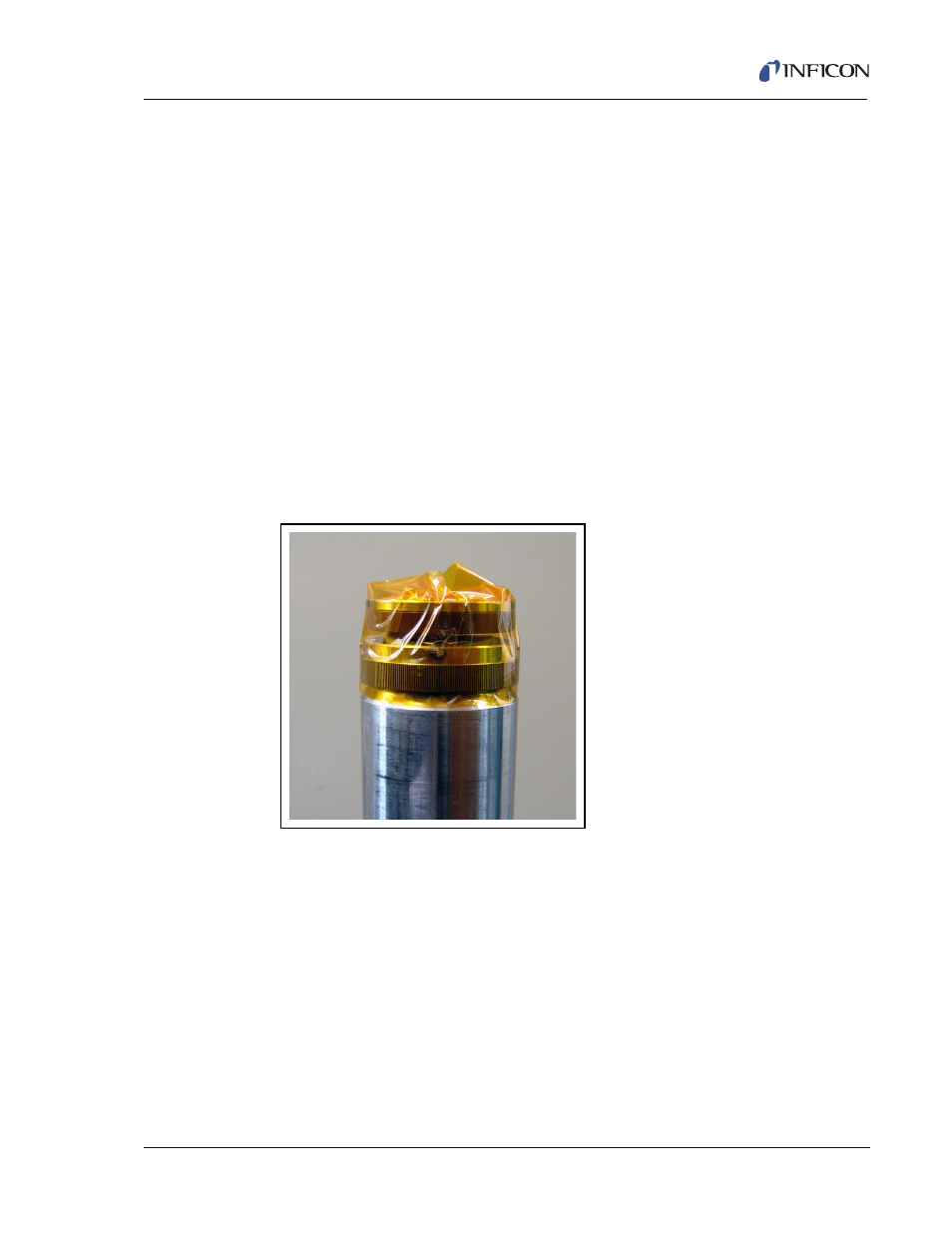
6
Position the Kapton tape with the bottom edge of the tape on the beveled
surface just below the knurled ring. Not starting at any of the three bayonet
pins, wrap the tape around the circumference of the sensor. Fold the excess
tape over the top of the Crystal Holder. See
.
Figure 2-3 Wrap Kapton Tape
7
Stand the RSH-600 sensor upright on a firm surface. Place the Adjustable
Flange, with smooth side up, over the top of the sensor barrel. With the flange
seating surface perpendicular to the sensor barrel, forcefully push the flange
downward, sliding the flange onto the sensor barrel. See