2 setup plc, 1 define plc inputs, 2 define plc outputs – INFICON Ecotec E3000 Multigas-Sniffer-Leak Detector Interface description User Manual
Page 12: Setup plc, Define plc inputs, Define plc outputs
12
2 I/O Port
In
te
rface D
e
scr
ipti
o
n
Ecotec E300
0,
k
ins
22e1
-j
, 1401
Recorder output gas
Here one gas from the four gases is defined which will be output as the analog signal
through channel 1.
Selecting one of the numbers 1 … 4 outputs the corresponding gas 1 … 4 on the display
as the analog signal.
Channel 2 (pin 14 of the I/O port) indicates the gas number by way of a voltage, i.e. a
voltage between 1 … 4 V will be present accordingly.
When selecting “auto” the leak rate which has the highest value with reference to the
corresponding trigger level is output as the analog signal. Correspondingly the voltage in
channel 2 will differ accordingly.
In the modes "ERROR”, "NOT READY TO MEASURE” and "SLEEP” a voltage of U = 10 V will
be output through channels 1 and 2.
Default setting: auto
2.2.2
Setup PLC
In the “Setup PLC” submenu you can define the PLC Inputs and PLC outputs.
2.2.2.1
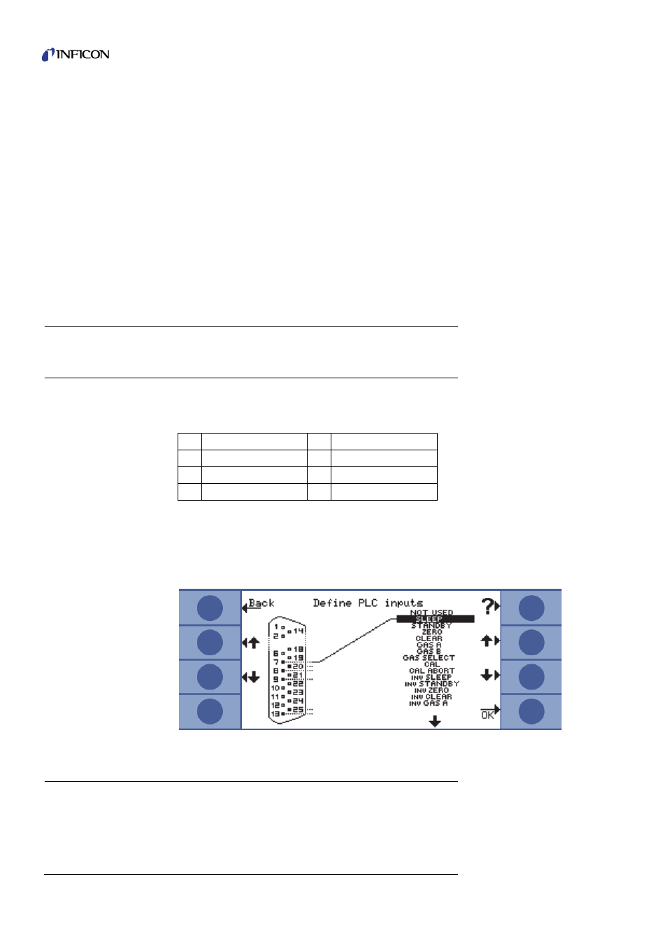
Define PLC Inputs
In the “Define PLC Inputs” submenu the user can define which pin on the I/O port (suitable
for PLC input) represents which command. The default setting is as follows:
To change these settings select the appropriate pin with the UP and DOWN arrows on the
left side of the display and afterwards select the desired command from the list of
commands with the UP and DOWN buttons on the right side of the display. Press OK to
save your settings. A screen with all selected settings will be displayed for your reference.
Confirm with OK again.
Fig. 3: Defining PLC-Inputs from list of possible commands
2.2.2.2
Define PLC Outputs
In the “Select PLC Outputs” submenu the user can define which pin on the I/O port
(suitable for PLC output) represents which command. There are four PLC outputs and two
relays outputs available. The default setting is as follows:
Table 5: PLC input, pin - command assignment
Pin
Command
Pin
Command
7
Sleep
13
Gas b
8
Not used
20
Zero
9
Gas a
25
Gas select