INCRA Wonder Fence User Manual
Page 4
4
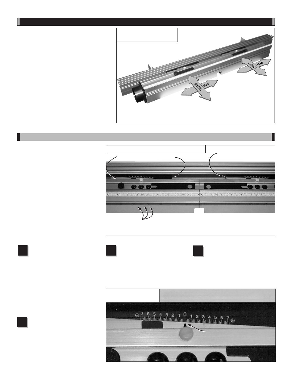
Fig. 6
Offset and gap adjustments
Referring to
Fig. 7, use the
supplied hex key to loosen the two
socket head screws through the
large holes in the front of each Wonder
Fence half . Also loosen the wedge
locking screw . The access hole for the
wedge locking screw is located between
the two large holes . For a clear view of
the screw heads, loosen the thumbscrew
and slide the black view panel located
on the top of the Wonder Fence . Loosen
each of the (3) screws one full turn .
Slide the black rear wedge on each
fence to align the ends of the rear
wedge flush with the ends of the
front wedge . This positions the wedges
at mid-range .
CauTIOn: To avoid
disengaging the nut, do not loosen any
of the socket head screws more than one
or two full turns.
In order for the etched scales on the
two black rear wedges to provide an
accurate readout of fence offset, the two
fences must first be positioned in-line
with one another with the adjustment
wedges at mid-range . The two cursors
can then be positioned to read zero on
the wedge scales . Once these cursors
are set, you’ll find it easy to return the
fences to the in-line/mid-range position
for standard in-line fence applications .
Here’s how .
Tighten all fasteners, then test
the in-line setup by sliding a
straightedge down the length of
the fences . If any offset exists, fine-tune
by adjusting the wedges on the outfeed
fence .
Make sure to tighten all
fasteners after each adjustment.
Fig. 7
Calibration: In-line/mid-range position
FIRST: Loosen (3) socket head screws
through access holes in each fence half.
SECOND: Align ends of
front and rear wedges
THIRD: Tighten all fasteners and
test with a reliable straightedge.
Fine-tune outfeed fence as necessary.
Outfeed fence
Infeed fence
Calibration: In-line/mid-range Position
Once the fences are located
in-line with one another, loosen
the nylon screw that secures
the cursor on each fence half and slide
the cursor to point to “0” on the etched
scale,
Fig. 8 .
1
2
3
4
Fig. 8
Slide cursor to read “0”
With fences in-line, loosen
nylon screw and slide cursor to
read zero on each fence half.
Rear wedge
OPeraTIOn
The infeed and outfeed fences of the
Wonder Fence can be moved independently
in two directions to provide a variety of
setup configurations . By making the
offset
adjustments described on page 5, you can
position the fences “in-line” for standard
operations such as grooving, rabbeting, or
joint-making, or you can “offset” the infeed and
outfeed fences for speciality cutting applications
such as shaping or jointing an edge . The
gap
adjustment allows adjustment of the opening
between the infeed and outfeed fences . Follow
the step-by-step instructions below to first
calibrate your Wonder Fence, then follow the
step-by-step procedures in the offset and gap
adjustment sections to familiarize yourself with
these two important functions shown in
Fig. 6 .
Front wedge