Warranty – INCRA Miter 1000SE User Manual
Page 7
INCRA MITER1000SE OWNER’S MANUAL
©2008 by Taylor Design Group, Inc. All rights reserved. Rev.07.08.08
Page 7
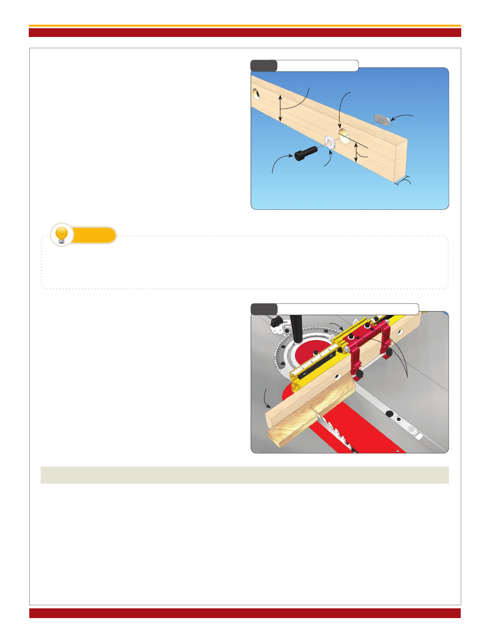
Making a Zero Clearance Wooden Sub
Fence
A sub fence can be used to provide tear out control
as well as support for your workpiece up to and be-
yond the blade. A good material to use for making
your zero clearance sub fence is
3/4
” medium density
fiberboard (MDF). Use the drill and counter bore di-
mensions shown in
Fig. 18. Attach using the supplied
fasteners. Adjust the length of the fence to accom-
modate your application. Note: In applications where
the incremental stopping capability of the Flip Shop
Stop is required, the wooden sub fence can be no
taller than 2-
1/2
”.
Expanded Flip Stop Clamping Mode
The two-part body design of the INCRA Flip Shop
Stop allows for use with up to a
3/4
” thick wooden sub
fence. To expand the INCRA Flip Shop Stop, loosen
the (2) socket head screws located on the top of the
stop body, then slide the upper portion of the stop
off. Now slide the upper portion back on, capturing
the rectangular nuts in the second T-slot located on
the lower portion (gold component) of the stop body,
Fig.19.
To avoid the saw blade pulling your workpiece into the cut, add a strip of adhesive backed sandpaper to the front
face of the wooden sub fence.
TIP
WARRANTY
TAYLOR dESIgN gROUP, INC. WARRANTS ThIS PROdUCT FOR ONE YEAR FROM dATE OF PURChASE. WE
WILL REPAIR ANY dEFECTS dUE TO FAULTY MATERIAL OR WORkMANShIP, OR AT OUR OPTION, REPLACE
ThE PROdUCT FREE OF ChARgE. PLEASE RETURN ThE FAILINg COMPONENT ONLY, POSTAgE PREPAId,
ALONg WITh A dESCRIPTION OF ThE PROBLEM TO ThE AddRESS BELOW. ThIS WARRANTY dOES NOT
APPLY TO PARTS WhICh hAvE BEEN SUBJECTEd TO IMPROPER USE, ALTERATION, OR ABUSE.
LIFETIME WARRANTY ON POSITIONING RACKS
IF AN INCRA POSITIONINg RACk IN ThIS TOOL BECOMES dAMAgEd FOR ANY REASON, TAYLOR dESIgN
gROUP WILL REPLACE IT FREE OF ChARgE FOR AS LONg AS YOU OWN YOUR TOOL. RETURN ThE dAM-
AgEd RACk, POSTAgE PREPAId, PLEASE ALLOW 1 TO 2 WEEkS FOR dELIvERY.
Fig. 18
Making a Sub Fence
Fig. 19
Expanded Flip Stop Clamping Mode
2
1/2
” max (see note)
5/16
” through hole w/
3/4
” dia. x
3/8
” deep
counter bore
1/4
-20
rectangular nut
1/4
” flat washer
1/4
-20 x
3/4
”
socket head screw
1
1/16
”
3/4
”
Gold component
Loosen socket head
screws and slide red
assembly into 2
nd
T-slot
on gold component
Sub fence