Assembly and calibration, 20 fasteners, fig. 5 – INCRA Miter 1000SE User Manual
Page 2
INCRA MITER1000SE OWNER’S MANUAL
Manufactured by Taylor Design Group, Inc. P.O. BOX 810262 Dallas, TX 75381
W W W . I N C R A . C O M
Page 2
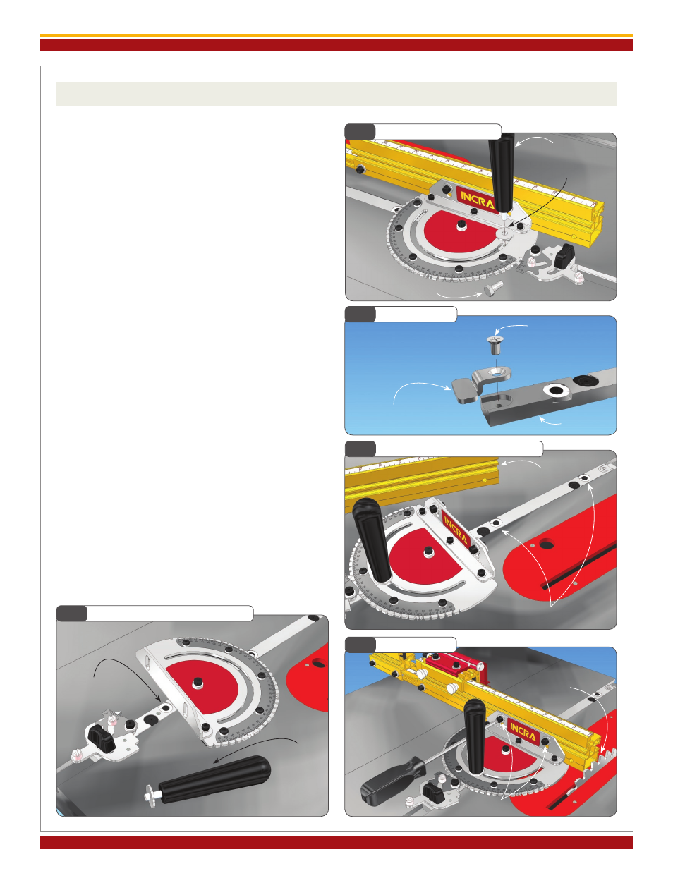
Assembly and Calibration
1. Attach Clamping Knob and T-Clip
Remove the hex bolt that secures the protractor head
and replace with the large threaded knob included in
the hardware pack. The washer on the hex bolt must
be used with the threaded knob,
Fig. 1. If the Miter
slot in your table saw has a T-slot, attach the T-clip to
the end of the miter bar as shown in
Fig. 2.
2. Adjust the Miter Bar
Loosen the (2) fasteners that secure the fence to the
fence-mounting bracket and remove the fence. Adjust
the miter bar at each of the (3) expansion mechanism
locations in the miter bar for a good fit in your table
saw’s miter slot. Turning the screw clockwise expands
the mechanism. You’ll find (2) of the expansion loca-
tions in front of the protractor. Adjust these (2) front
expansion points first, expanding a little at each of the
locations until the bar slides smoothly,
Fig. 3.
Remove the large clamping knob with washer and
pivot the protractor head to gain access to the rear
expansion point,
Fig. 4. After adjustment, replace the
washer and large clamping knob.
3. Attach the Fence
Place your Miter1000SE in the preferred miter slot
at your table saw. (Note: Left hand miter slot use
shown. See step 4 to convert fence for use in right
hand miter slot.) Attach the fence to the fence mounting
bracket and slide the fence to a position that leaves
safe clearance between the end of the fence and the
blade. Tighten the (2)
1/4
-20 fasteners,
Fig. 5.
Fig. 1
Attach Clamping Knob
Fig. 2
Attach T-Clip
Fig. 3
Expand Miter Bar to Fit (front)
Fig. 4
Expand Miter Bar to Fit (rear)
Fig. 5
Attach Fence
Large knob
Washer
Remove hex bolt
Miter bar
#10-24x
1/4
”
Phillips flat head
screw
T-clip (use only in T-slot
miter channels)
Fence removed for
access
Adjust (2) front expansion points
1/4
-20 socket head screws
Position for safe
clearance between fence
and blade
Adjust rear
expansion point
Remove knob
and rotate
protractor for
access.
Replace after
adjusting
rear expansion point.