Between the two stop positions – INCRA Miter 1000SE User Manual
Page 6
INCRA MITER1000SE OWNER’S MANUAL
Manufactured by Taylor Design Group, Inc. P.O. BOX 810262 Dallas, TX 75381
W W W . I N C R A . C O M
Page 6
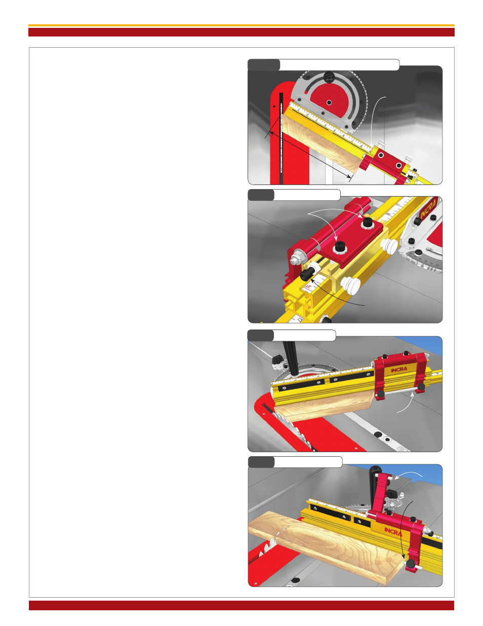
For mitered cutting, a test cut is often the most ac-
curate means of setting the fence and extender bar
scales since measuring to the tooth of a blade set at
an angle to the fence can be difficult. Begin by setting
the desired miter angle and check for safe clearance
between the fence and blade. Clamp the stop to the
fence about 10” away from the blade. Miter a piece of
scrap stock with this setup. Measure the length of the
cut piece,
Fig. 14B. Then simply slide the scale on
the fence to read the length of the cut directly under
one end of the stop.
Micro Adjusting
To micro adjust your Flip Shop Stop’s position, begin
by loosening the (2) socket head screws located on
the top of the stop body. Now turn the micro adjust
socket head screw to fine tune the stop position,
Fig. 15. When unscrewing the micro adjust screw,
apply pressure to the stop body to keep it against the
screw end. After adjustment, always tighten the (2)
socket head screws on top of the stop body.
Flip Arms and Stop Rods
The dual flip arms and stop rods provide a variety of
stop configurations. The flip arms can be used without
the stop rods when you want to take advantage of the
fence/arm tongue and groove feature for stop control
on mitered board ends. Typically, you will use the
longer rod to join the two arms together,
Fig. 16. This
produces an arrangement that, when pivoted, moves
both arms simultaneously. The rod can be positioned
so that it is the actual stop surface or it can be posi-
tioned slightly behind the front of the arm so that the
aluminum arm is the actual stop surface.
By placing one of the shorter 1-
1/2
” rods in each of the
two stop arms, you can use the two stop arms in-
dependently,
Fig. 17. For example, you can calibrate
one for work to the left of the blade and the other
for work to the right. On one side of the blade you
might want to position the stop rods to provide two
different cut off lengths from one stop position. By
using varying combinations of long or short rods you
can create as much as 7-
3/4
” between the two stop
positions.
Fig. 14B
Setting Scales for Angled Cuts
Fig. 15
Micro Adjusting
Fig. 16
Long Stop Rod
Fig. 17
Short Stop Rods
Slide scale to read
cut length here
Measure length
of cut
Loosen (2) socket
head screws
Turn this socket head screw
to adjust
Long stop rod used to
join flip arms
Short stop
rods allow
independent
flip arm
use