Block diagram, System manual safety system ces-a-w5h-01 – EUCHNER CES-A-W5H-01 (Multicode) User Manual
Page 7
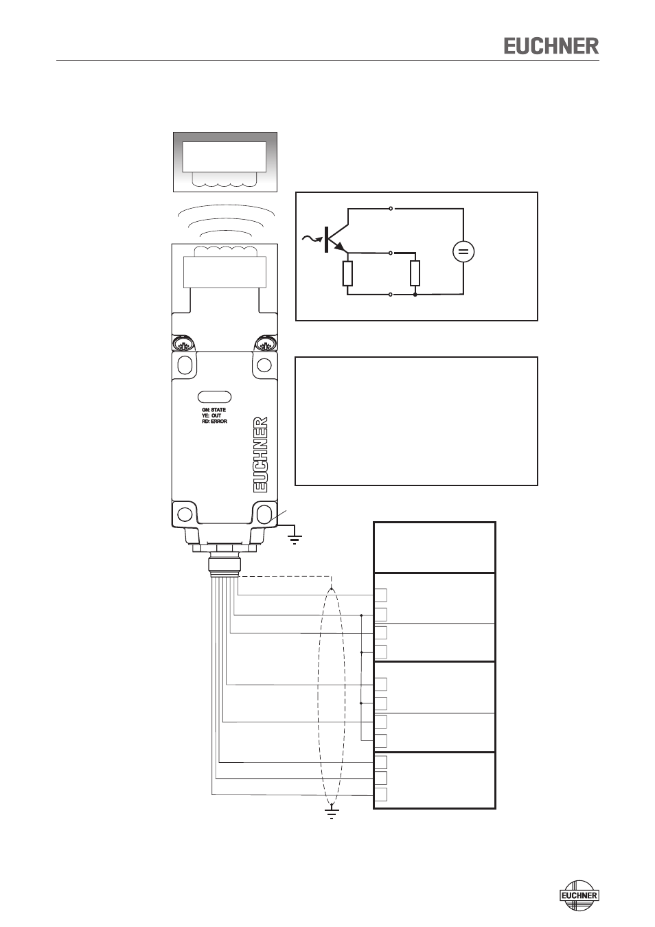
System Manual Safety System CES-A-W5H-01
7
Block diagram
1
2
3
4
5
6
7
8
0V
+ U
LA
LB
OUT
+LA
-LAB
+LB
B
I1
O1
0 V
0 V
E2
I9
O9
0 V
0 V
0 V
OUT
DC +24 V
+LB
-LAB
LB
+LA
LA
+ U
0V
(RD)
(BU)
(YE)
(PK)
(GN)
(GY)
(BN)
(WH)
+LA
LA
R
B
-LAB
+
-
Trans-
ponder
Pin assignment:
Common ground for output A and B
Load A
Pin
Core color
WH/white
BN/brown
GN/green
YE/yellow
GY/gray
PK/pink
BU/blue
RD/red
Function
Coded
actuator
Read head with
evaluation unit
CES-A-W5...
Housing:
118 x 40 x 40 mm
Connection:
M 12x1
8-pin, screened
Read head
Safety input
Pulsed output
Input
Safety input
Pulsed output
Output circuit:
Screen bonding clamp
The screen on the connection cable
is connected internally to the screen
bonding clamp on the housing.
Safety PLC
with static /
dynamic signals
Connection example with safety PLC
Power
supply
for load A
Test pulse 0
Test pulse 1
- N1A Single hole fixing limit switch (12 pages)
- NZ Safety switch (12 pages)
- NZ.VZ (15 pages)
- NZ.VZ-xxxVS (16 pages)
- TZxxxAS1 (16 pages)
- TZxxx (20 pages)
- NXxxx (12 pages)
- TXxxx (12 pages)
- SGAxxx (12 pages)
- STAxxx (15 pages)
- STA-TWxxx (Twin) (15 pages)
- NMxxAV/AL (8 pages)
- NMxxWO/RB (12 pages)
- NMxxKB (12 pages)
- NMxxHB (12 pages)
- NMxxAK/AG (8 pages)
- NMxxVZ (15 pages)
- NP (12 pages)
- GPxxx (12 pages)
- TPxxx (12 pages)
- SGPxxx (12 pages)
- SGP-TWxxx (Twin) (12 pages)
- STP-TWxxx (Twin) (15 pages)
- STPxxx (15 pages)
- STP-BIxxx (12 pages)
- STMxxx (12 pages)
- NQxxVZ (8 pages)
- TQxxx (12 pages)
- TKxxx (12 pages)
- ESH (8 pages)
- Hinge ESH Re-adjustable (8 pages)
- MGB-AR (14 pages)
- MGB-L1-xxxARx-xxx (38 pages)
- MGB-L0-xxxARx-xxx (36 pages)
- MGB-LxxB-PNx-xxx (PROFINET) with Data Structure Type B (44 pages)
- MGB-LxxB-PNA-xxx (PROFINET) with Data Structure Type A (36 pages)
- CES-A-ABA-01 (Unicode) (42 pages)
- CES-Axxx (5 pages)
- CES-A-AEA-02B (Unicode) (44 pages)
- CES-A-UBA-01 (Multicode) (40 pages)
- CES-A-UEA-02B (Multicode) (44 pages)
- CES-AZ-ABS-01B (Unicode) (40 pages)
- CES-AZ-UBS-01B (Multicode) (38 pages)
- CES-AZ-AES-xxx (Unicode) (54 pages)
- CES-AZ-UES-xxx (Multicode) (56 pages)