System manual safety system ces-a-w5h-01, Technical data, Ordering table – EUCHNER CES-A-W5H-01 (Multicode) User Manual
Page 20
System Manual Safety System CES-A-W5H-01
0
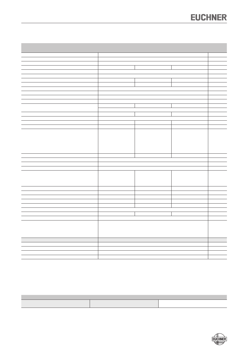
Technical Data
Parameter
Value
Unit
min.
typ.
max.
Housing material
Plastic PBT V0 GF30
Dimensions
According to EN 60947-5-
mm
Weight
0,4
kg
Ambient temperature at U
B
= DC 4 V
-0
-
+55
°C
Degree of protection
IP67
Degree of contamination
3
Rated insulation voltage U
i
-
-
300
1)
V
Rated impulse withstand voltage U
imp
-
-
1,5
kV
Rated conditional short-circuit current
100
A
Resilience to vibration
According to EN 60947-5-
Installation position
Any
Connection type
M1 plug connector, 8-pin, screen can be applied
Operating voltage U
B
(regulated, residual ripple < 5 %)
18
4
7
V DC
For the approval according to UL the following applies
Operation only with UL Class power supply, or equivalent measures
Current consumption
80
mA
Switching load according to UL
max. DC 4 V, class
External fuse (operating voltage U
B
)
0,5
-
8
A
Power supply for load U(+LA)/U(+LB)
18
-
7
V DC
Safety outputs (LA / LB, semiconductor outputs, p-switch-
ing, short circuit-proof, electrically decoupled)
- Output voltage U(LA/U(LB)
)
HIGH U(LA)
U(+LA) - 1.5
-
U(+LA)
HIGH U(LB)
U(+LB) - 1.5
-
U(+LB)
V DC
LOW U(LA)/U(LB)
0
-
1
Switching current per safety output
1
-
400
mA
External fuse (U(+LA)/U(+LB), safety circuit
400 mA medium slow-blow
Utilization category to EN 60947-5-
DC-13 4V 400mA
Classification according to EN 60947-5-3
PDF-M
Door monitoring output (OUT, semiconductor output, p-
switching, short circuit-proof)
- Output voltage
0.8 x U
B
-
U
B
V DC
- Max. load
-
-
0
mA
Switching delay from state change
3)
-
-
180
ms
Discrepancy times of both safety outputs
-
-
10
ms
Ready delay
4)
-
-
3
s
Dwell time
5)
0,5
-
-
s
Switching frequency
-
-
1
Hz
Repeat accuracy R according to EN IEC 60947-5-3
≤ 10
%
Mounting distance between read heads or actuators
80
-
-
mm
EMC protection requirements
In acc. with EN 60947-5-3
LED displays
STATE
Green LED: Normal operation
OUT/ERROR Yellow LED: Actuator detected
OUT/ERROR Red LED:
- EMC interference
- Internal electronics fault
- Invalid teach-in operation
Reliability figures according to EN ISO 13849-1
Category
4
Performance Level (PL)
PL e
PFH
d
3,7 x 10
-9
/ h
6)
Mission time
0
years
1) Tested by BG up to 75 V.
) Values at a switching current of 50 mA without taking into account the cable lengths.
3) Corresponds to the risk time according to EN 60947-5-3. This is the maximum switch-off delay for the safety outputs following removal of the actuator.
4) After the operating voltage is switched on, the semiconductor outputs are switched off and the monitoring outputs are set LOW during the ready delay.
5) The dwell time of an actuator inside and outside the operating distance must be at least 0.5 s to ensure reliable detection of internal faults in the evaluation unit (self-monitoring).
6) Applying the limit value from EN ISO 13849-1:008, section 4.5. (MTTF
d
= max. 100 years), BG certifies a PFH
d
of max. .47 x 10
-8
.
Ordering table
Series
Category according to EN ISO 13849-1
Order no. / item
CES-A-W5...
4
097525
CES-A-W5H-01