Transient voltage surge suppression – ERICO 200 Series SES User Manual
Page 2
SES 200 Series
Transient Voltage Surge Suppression
2000 ERICO
Inc, 34600 Solon Rd, Solon, OH 44139
Page 2 of 4
Doc: IPSES200.doc, Issue: A, Date: 9/13/2000
DISCONNECT / LOCKOUT POWER
Disconnect and lockout power to the point where the
SES 200 is to be installed. Follow all applicable
electrical codes and safe working practices.
INSTALLATION
PHYSICAL LOCATION
1. The SES 200 should be installed as close as
possible to the service switchboard, switchgear,
power distribution panelboard or other determined
connection point. The location should be chosen to
keep the interconnecting wiring as short as possible.
Any sharp bends in the wiring should be avoided.
ENCLOSURE MOUNTING
2. The SEP 200 should be mounted utilizing the four
mounting holes provided as part of the enclosure.
Mount the SES 200 securely and rigidly to the
surface or structural member.
CONDUIT HOLE LOCATION
3. The conductors should exit the enclosure at the top
of the enclosure above the wiring terminals. The
hole should be sized appropriately for the desired
conduit fittings. If the conductors are required to exit
the enclosure through the top wall, the hole should
be placed directly above the terminals. If the
enclosure is being located directly adjacent to a
panelboard, the hole should be placed on the right
or left side of the enclosure within 2” of the top. A
straight nipple may be used; otherwise an
appropriate conduit connector should be used.
If remote alarming is required, an additional hole
may need to be made for connection to the alarm
contacts.
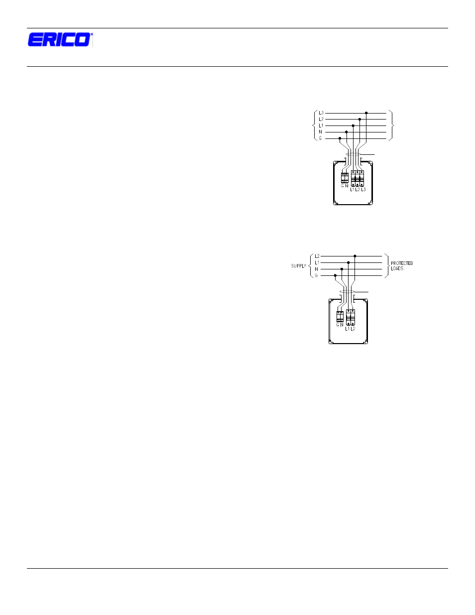
WIRING DIAGRAM
4. The wiring diagrams below show how the SES 200
is to be wired. This TVSS device is wired in parallel
with the distribution system be protected. The SES
200 is supplied with a fuse holder with integral
overcurrent protection. Additional external
overcurrent protection is not necessary.
The recommended wire size for the SES 200 Series
TVSS is #6 AWG and a #6 AWG ground. When
terminating the wiring on the SES terminals, strip the
insulation ½,” insert into the terminal and then
tighten to a torque of 35 in-lbs.
Figure 1. SES 200 Three-Phase Wiring Diagram
Figure 2. SES 200 Single-Phase Wiring Diagram
INDICATORS
5. The SES 200 has TDS
-MOVTECs as the TVSS
elements. Each of these MOVTECs has a 5 LED
bar graph arranged so that they are visible through
the front of the enclosure. When all 5 LEDs on each
MOVTEC are illuminated, the protection circuitry is
operating correctly for that line. If one LED has
extinguished, the Surge Protector has sustained a
surge, which has reduced the remaining capacity,
and the protection has been compromised. If two
LEDs are extinguished, the surge capacity has been
reduced to 60% of total capacity. The alarm relay
will drop out at this point. While there is still some
protection provided, the Surge Protector should be
replaced as soon as possible.
(3)#6, #6 GND
(4)#6, #6 GND
Protected
Loads
Supply