ERICO TDS-DINLINE Surge Suppressor User Manual
Page 25
PAGE 25
ALARM TESTING
Testing of the Alarm Relay which is connected
to a fully functional Surge Suppressor unit
can be accomplished by removing power to the
Surge Suppressor only. The Alarm Relay
Status indication and output contacts should
alter from the Normal to Fault condition.
Testing of the Alarm Relay unit alone may be
accomplished by disconnecting the + / -
connections to the unit. When power is applied
the “Fault” Status Indicator should be
illuminated. By connecting the + / - terminals
together, the “Normal” Status Indicator should
be illuminated. The output contacts should
alter to the appropriate state.
USE OF OTHER INTERFACES
Only ERICO TDS-AR units are recommended
for the interfacing of equipment to the TDS-
DINLINE opto-coupler alarm output circuit.
The direct connection of other equipment to the
opto-coupler alarm output circuit may not
provide sufficient isolation or exceed the opto-
coupler specifications. This may damage the
Surge Suppressor and/or the connected
equipment. Warranty may be voided under such
circumstances.
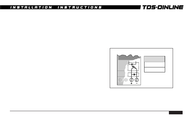
Opto-
coupler
Protection
diode
SURGE SUPPRESSOR OPTO-COUPLER ALARM
Opto-coupler
Vce =
30V DC
Ic =
150 mA
Note: TDS XXX-4S and
TDS XXX-8S have
respectively 2 and 4
opto-couples connected
internally in series.