ERICO TDS-DINLINE Surge Suppressor User Manual
Page 16
PAGE 16
D S D I N S T A L L A T I O N I N S T R U C T I O N S
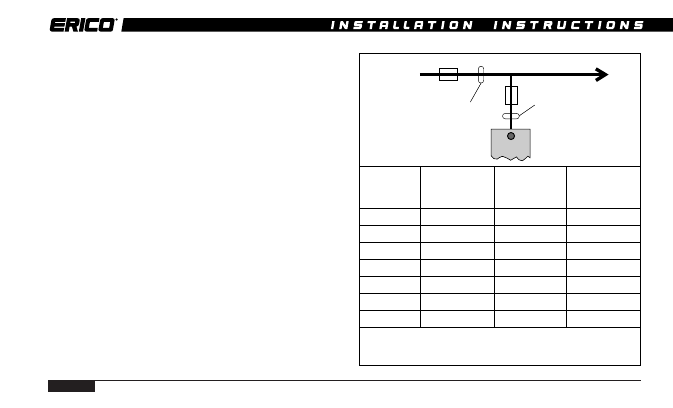
For Surge Suppressors installed in the “non-
preferred” connection method (page 13),
depending upon the size and fusing in the
main circuit, the “T” connection may require
independent fusing to be installed.
Circuits with upstream protection rated at
greater than 100A must have a 100A HRC
fuse or circuit breaker installed in the T
connection as detailed by the following
diagram.
Warning:
Isolation/fusing installed in the “T” connection
may disconnect the Surge Suppressor from the
circuit/equipment to be protected. The remote
alarm contacts of the ALARM RELAY (TDS-
AR) should be used to detect this occurrence.
Operation of the isolation/fuse will remove the
protection from the circuit.
Ph
A mm
2
B mm
2
Supply
Upstream*
T-Connection Required
Conductor Protection Size
T-Connection
Size
Fuse
A mm
2
A fuse rating B mm
2
B fuse rating
1.5 mm
2
16A
1.5 - 6 mm
2
Nil
2.5 mm
2
20A
2.5 - 6 mm
2
Nil
4.0 mm
2
25A
4 - 6 mm
2
Nil
6.0 mm
2
32A
6 mm
2
Nil
>6.0 mm
2
<100A
6 mm
2
Nil**
>6 mm
2
>100A
6 mm
2
100 A**
* Fuse rating A selection based on maximum current carrying capacity of
conductor. Smaller rating fuse may be selected ir required.
** Short circuit protection selection based on I
2
t rating of cable and fuse.
A
B
Supply