Cadweld, Propulsion rail - web bond – ERICO CADWELD Propulsion Rail - Web Bond User Manual
Page 3
Disk
!
!
WARNING:
Back-to-back bonding of web bonds is strictly
forbidden! Bonds made on the opposite side of the rail to
an earlier web bond must be applied at least two inches away
(centerline to centerline) from the earlier bond to avoid serious
structural harm to the rail. Failure to observe this may result in a
rail break leading to property damage, injury or death to others.
IV. WELDING PROCEDURE
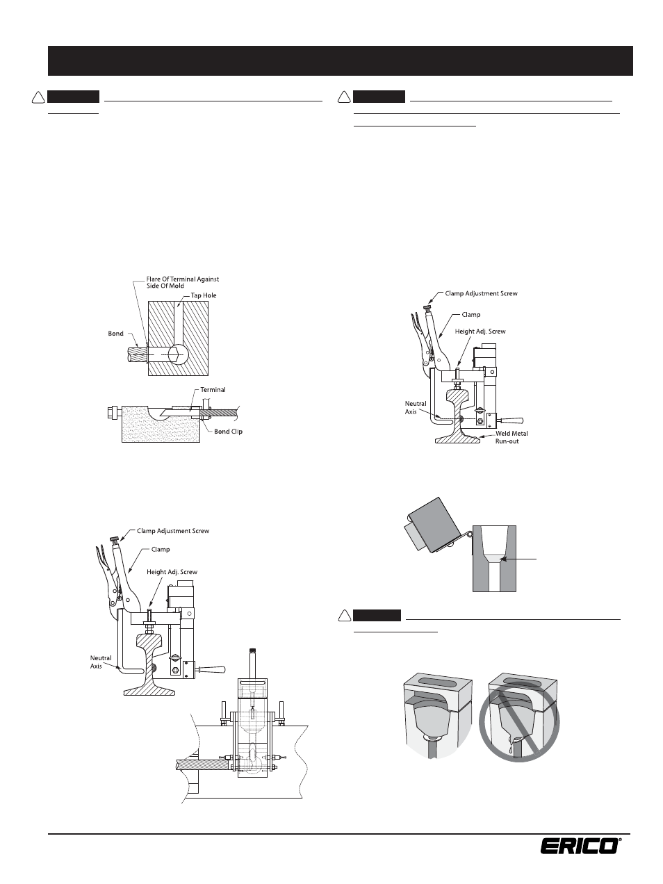
1. Place bond in welder with fl at surface against rail web and
end of terminal against bond clip. This correctly positions
the bond in the weld cavity. Be sure the bond clip is in good
condition and properly positions the terminal under the center
of the tap hole as shown. See Figure 7.
WARNING:
Correctly positioning the mold against the
rail web with the welder device is critical for safety and
success in making a bond. There must be no cracks between
the lower part of the mold that contains the weld cavity and the
rail surface; if a crack is present, the mold should be discarded
and a new one used. See Figure 10. (Molds can generally be
used for up to 50 welds.) The exothermic reaction reaches a
temperature in excess of 4000°F, therefore great care must
be exercised to avoid spillage of the molten metal. Failure to
observe this warning may result in molten metal leakage onto
the rail with the immediate risk of personal injury, and potentially
serious structural damage to the rail. Failure to locate the bond
at the neutral axis of the rail may also contribute to premature
rail damage. Either could result in a rail break leading to
property damage, injury or death to others.
T20-Clamped Position
2. Position the welder with attached mold on the rail.
Use the mold height adjusting screw of the positioning bar
to locate the bond terminal at the neutral axis of the rail.
See Figures 8 and 9.
3. Insert one steel disk, dished (concave) side up, in the crucible
to cover the taphole. See Figure 11.
FIGURE 7
FIGURE 8
FIGURE 9
FIGURE 10
FIGURE 11
www.erico.com
3
CADWELD
®
Propulsion Rail - Web Bond
Refer to the mold tag for applicable instruction sheets.
IPRPW_C
!
CAUTION:
The steel disc must be correctly installed into
the mold crucible. Failure to properly position it may result
in premature leakage into the mold area, resulting in an
unacceptable weld. See Figure 12.
FIGURE 12
4. Dump the contents of the welding material container into
the crucible, being careful not to upset the disk.