Enerpac BMS-Series User Manual
Page 6
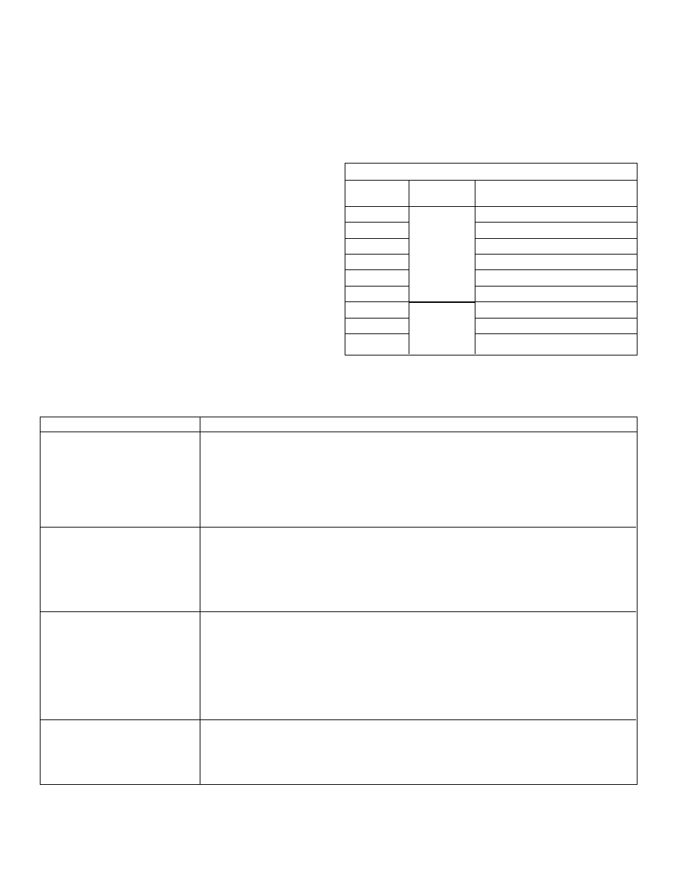
Cylinder will not advance
Cylinder leaks oil
Cylinder will not retract
LEDs of the electronic position
control do not light up
6
2B. RESET SWITCH FOR RETRACTED POSITION: switch is
factory set at the end of retracted plunger stroke. If you want
the plunger movement to stop 3 mm before the end of
retracted stroke, the proximity switch must be moved 3 mm.
3.
Check the correct functioning of the position monitoring by
activating the block cylinder hydraulically. The green LED
indicates the activated switch of the retracted position, the
red LED indicates the activated switch of the extended
position.
4.
Re-assemble the cover plate to the switch box.
6.2 Electric Circuit
See illustration 4 - electric scheme of position monitoring and
Table C - specification proximity switch.
7.0 CYLINDER SPECIFICATIONS
See Table B for clamping force, stroke, oil capacity, etc. and
illustrations 5, 6, and 7 with Table D for cylinder dimensions.
8.0 ACCESSORIES
Contact bolts are available which can be attached to the plunger
end. See Table E for spherical and swivel models.
9.0 MAINTENANCE AND SERVICE
•
Regularly inspect all components to detect any problem
requiring maintenance and service. Replace worn or
damaged parts.
•
Do not exceed oil temperatures above 65 °C.
•
Use clean, high-quality, hydraulic oil in your system.
Contaminated oil causes premature wear to moving parts
and seals. Frequency of changing oil depends on operating
conditions and filters within your system but you should
follow a regular maintenance schedule. Dispose of used oil
properly.
Enerpac offers ready-to-use spare parts kits for repair and/or
replacements.
Table E - Contact Bolts
Model No.
Type
To be used with
cylinder capacities
BS-6
11 kN
BS-8
17 kN
BS-16
44 kN
BS-20
68 kN
BS-30
175 kN
BS-36
275 kN
BR-8
17 kN
BR-16
44 kN
BR-20
68 kN
Spherical
Contact Bolt
Swivel
Contact Bolt
A.
The sequence valve opening pressure is higher than the pump pressure. Adjust the
pressure setting fo the sequence valve.
B.
No oil or too low oil level in pump. Refill reservoir.
C.
Pump release valve open. Close pump valve.
D.
Couplers not completely connected. Check pump valve.
E. Plunger binding. Check cylinder internal parts.
F.
When you use the electronic position control, check if green light (LED) is activated.
A.
Worn or damaged plunger. Replace plunger and seals.
B.
Internal seals damaged. Replace seals.
C.
Leaking or loose oil connections.
D.
O-ring between manifold and cylinder worn or damaged. Check if surface roughness is
Ra 1,6 µm and replace O-ring.
E.
Check if torque of mounting bolts is according to Table A.
A.
Pump release valve colsed. Open this valve.
B.
couplers not completely connected. Check hydraulic line.
C.
Internal damage toplunger. Check parts.
D.
Broken spring. Replace spring.
E.
Back pressure in hydraulic system too high or return-spring is not strong enough.
Reduce back pressure by reducing the number of couplers, increasing the piping
diameter or by-pass the valving.
F.
when you use the electonic positioncontrol, check if red light (LED) is activated.
A.
Check if connections are according to specifications and diagram.
B.
Check the position of the proximity switches (§6).
10.0 TROUBLESHOOTING GUIDE
Problem
Solution