Enerpac BMS-Series User Manual
Page 3
3
3.0 Product Description
These cylinders are designed according to ISO standards and are
available as single-acting spring return and double-acting
cylinders. All cylinders have a plunger wiper and chrome plated
plunger. Each plunger has an internal thread to allow attachments.
The maximum operating pressure is 350 bar. These cylinders
generate from 10,9 kN to 274,8 kN of clamping force. BS and
BMS are single-acting cylinders, BD and BMD are double-acting
models. BS and BD cylinders have BSPP1/4" oil port connections.
BMS and BMD cylinders have o-ring manifold connections. for the
oil port locations, see illustration 5, 6, and 7.
All double-acting cylinders can be equipped with electronic
position monitoring. See §6.0 for description, specification and
adjustment of this electronic device.
4.0 APPLICATION
Hydraulic block cylinders can be used in many workholding
applications such as puling, pressing, punching, riveting and
bending. Using the electronic position monitoring (optional on
double-acting cylinders only), the adjustable retracted and
extended plunger monitoring positions can be detected by
inductive proximity switches (§6.0).
5.0 INSTALLATION
IMPORTANT: It is mandatory that the operator has a full
understanding of all instructions, safety regulations,
cautions, and warnings, before starting to operate any of
the equipment. In case of doubt, contact Enerpac.
WARNING: To avoid personal injury and possible
equipment damage, make sure the manifold or fixture, all
fittings and piping are able to withstand the maximum
operating pressure of 350 bar.
RECOMMENDATION: Use hydraulic gauges to indicate safe
operating pressures in each hydraulic system. Do not exceed the
safety limits of the lowest rated component within your hydraulic
system.
Depending on block cylinder model, two mounting options are
available. See illustrations 1 and 2.
CAUTION: When operating above 150 bar of hydraulic
pressure in applications, as shown in illustrations 1 and 2,
provide cylinder back-up using a support to eliminate
shear loads on the mounting bolts. This minimum support height
H is specified in Table A - Installation Information.
Illustration 1 - Manifold mounting: when hydraulic connections are
made through the standard integrated o-rings ports, the sealing
surface must have a maximum roughness of Ra 1,6 µm and a
flatness of 0,1 mm.
Illustration 2 - for all single-acting cylinders: if there is a risk of
machining coolants or debris entering the breather vent (port B), it
is recommended to pipe this port to an area outside the fixture
that is protected from machining coolants and debris.
6.0 ELECTRONIC POSITION CONTROL
All double-acting cylinders (BD and BMD) ending with suffix P are
provided with the electronic position monitoring device. The
electronic monitoring is achieved by two proximity switches,
detecting a vane which is assembled on top of the plunger. Both
proximity switches can be adjusted over the full plunger stroke
(see §6.1) and are assembled in a box, mounted on the cylinder
base.
Two LEDs indicate the plunger positions: the red LED indicates the
extend (clamp) position, the green LED indicates the retract
(unclamp) position. See illustration 3.
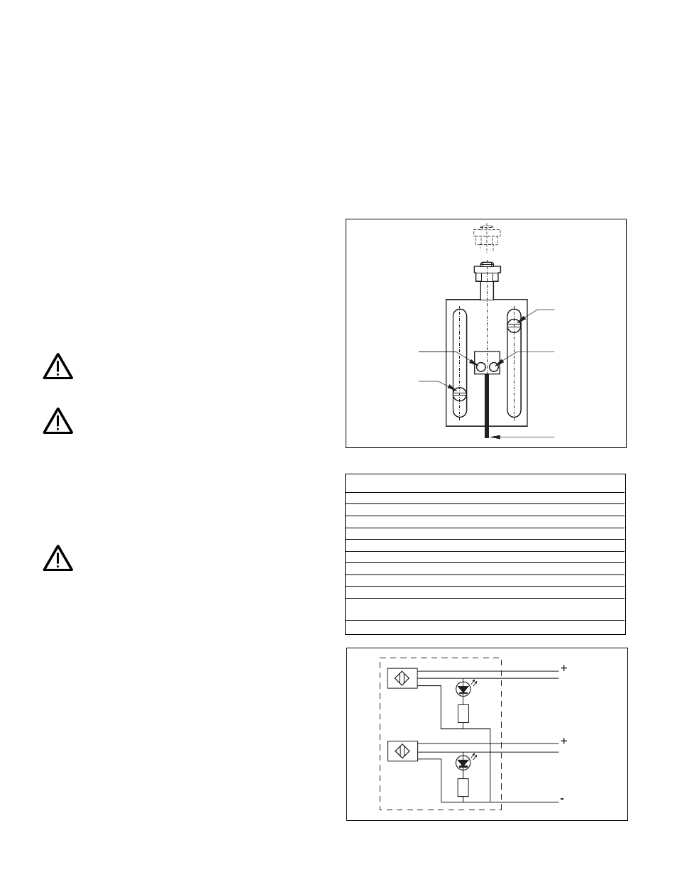
6.1 Proximity Switch Adjustment
To realize different switching points, the proximity switches can be
adjusted in a slot over the full plunger stroke (see illustration 3).
Follow the steps below to adjust the proximity switch positions.
1.
Remove the cover plate from the switch box.
2A. RESET SWITCH FOR EXTENDED POSITION: switch is
factory set at 5 mm before the end of the total plunger stroke.
Determining switching point and position is done by
calculating: full stroke - required stroke - 5 mm. Example: you
need a stroke of 30 mm, but total stroke is 50 mm.
Illustration 3 - Proximity Switch Adjustment
Table C - Specifications Proximity Switch
Type
PNP output, normally open
Supply voltage
4,75 - 30 VDC
Voltage drop
1 Volt maximum
Max. voltage fluctuation
10%
Turn-on current (no load)
10 mA maximum
Max. load current
100 mA
Leakage current
50 µA maximum
Ambient operating temp.
-10 to +65 °C
Protection
IP 67
Circuit protection
Protected against reverse polarity and
sustained short circuit.
Cable
5 x 0,14 mm
2
, PVC, 2 meters
Illustration 4 - Electric Scheme
Red LED
Switch for
retracted position
Switch for
extended position
Green LED
Wire
Extend
White
Grey
Output
Extend
Green
Brown
Yellow
Output
Retract
Retract
Green
Red