Enerpac ATM-2 User Manual
Page 3
3
4.0 OPERATING INSTRUCTIONS
1. Determine the maximum point of misalignment.
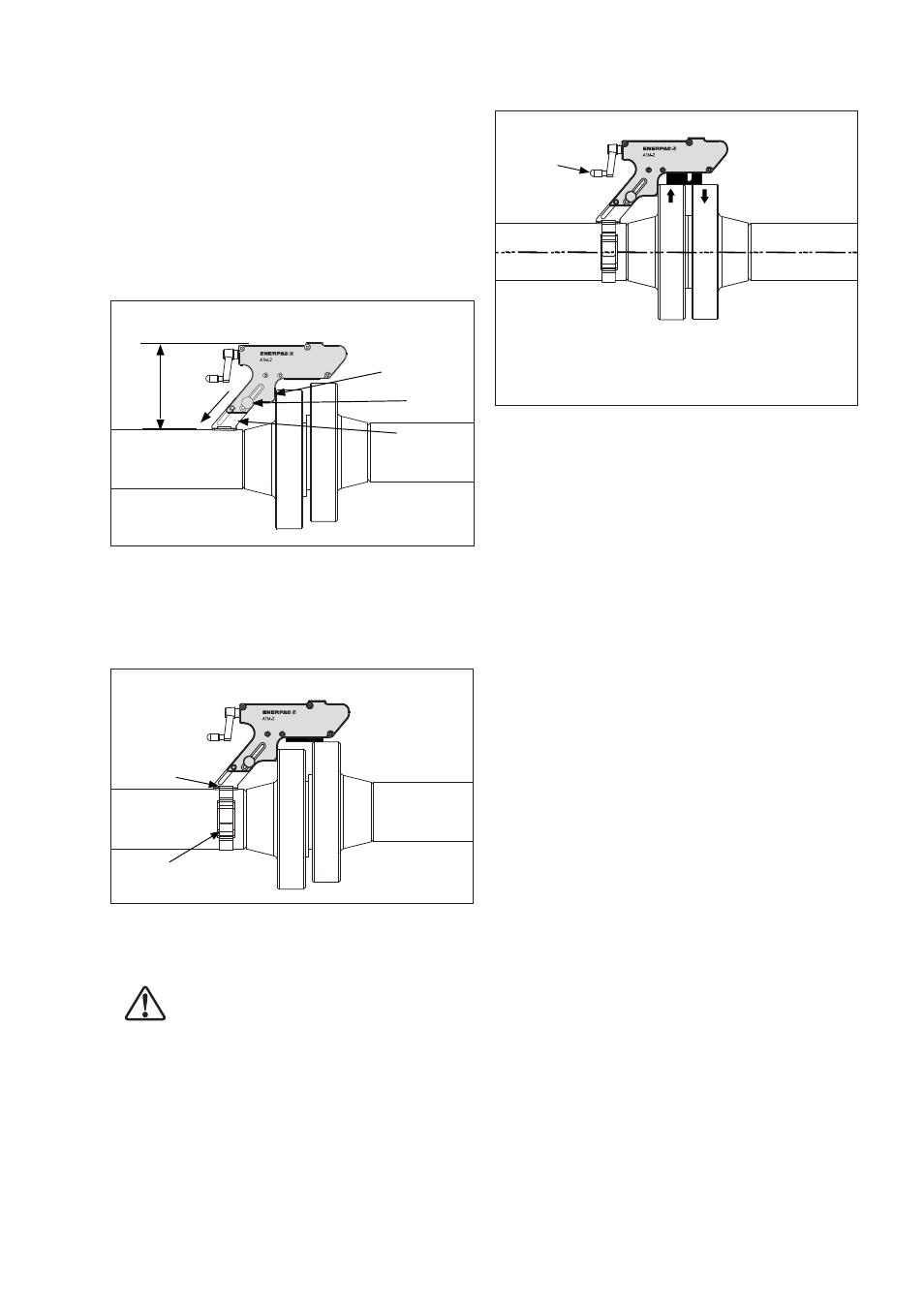
2. Guide the lift hook of the tool into the bolt hole
at the maximum point of misalignment. The drop
leg should be released and lowered onto the pipe
while the hook is held level in the bolt hole. It then
must be secured in position by tightening the
thumb screw. See Fig. 2.
PARALLEL
Fig. 2 Assembly of Tool on Flange
LIFT
HOOK
THUMB
SCREW
DROP
LEG
3. Rotate the screw handle clockwise until the driven
wedge makes contact with the opposite flange.
Thread the strap through the aperture on the base
of the drop leg, feed the end of the strap through
the buckle, and close the clasp. See Fig. 3.
Fig. 3 Strap Installation
STRAP
APERTURE
STRAP
4. Rotate the screw handle clockwise until alignment
is achieved. See Fig. 4.
WARNING: Do not exceed 45 lbf. [200 N]
hand pressure on the screw handle.
Handle may break if greater force is
exerted. Never use tools to turn the handle.
5. When alignment is completed, the flange bolts
may be inserted and tightened. After replacing all
of the bolts in all open bolt holes (except for the
bolt hole in which the tool lift hook is inserted),
remove the tool by reversing steps 1 through 4.
Fig. 4 Alignment
Maximum Recommended handle-
force = 45 lbf. [200 N].
OPERATE HANDLE BY HAND
ONLY - DO NOT USE TOOLS!
HAND
CRANK
6. After removing the tool from the flange, install the
last flange bolt in the remaining bolt hole.
5.0 EXAMINATION - MAINTENANCE
• After finishing the job and before the tool is placed
back into service, the completeness of the ATM-2
tool must be established and items examined to
ensure that they are serviceable.
• Any missing or damaged items are to be replaced
as soon as possible and prior to the tool being
used again.
• Grease all moving parts regularly with Mobilgrease
XHP ™ 222 Special grease. Refer to Section 6.0.
• Return all items to the carrying case when not in
use.
6.0 INSPECTION AND LUBRICATION
(See Fig. 5 on next page)
STEP 1. Place tool flat on work bench.
STEP 2.
Using a small, flat screwdriver, remove
circlip. Then, remove five 4mm hex screws.
STEP 3.
Remove cover plate and remove any dirt
or corrosion from moving parts.
STEP 4.
Inspect components for wear and damage.
Replace as required. If no damage is
present, then grease and reassemble
parts by reversing steps 1 through 4.
Note: Use Mobilgrease XHP ™ 222 Special grease
or an equivalent good quality high load bearing
grease.