Communications, Can communication (j2) – ElmoMC Gold Line Digital Servo Drives-Gold Trombone User Manual
Page 68
Gold Trombone Installation Guide (EtherCAT and CAN)
Installation
MAN-G-TROIG-EC (Ver. 1.604)
68
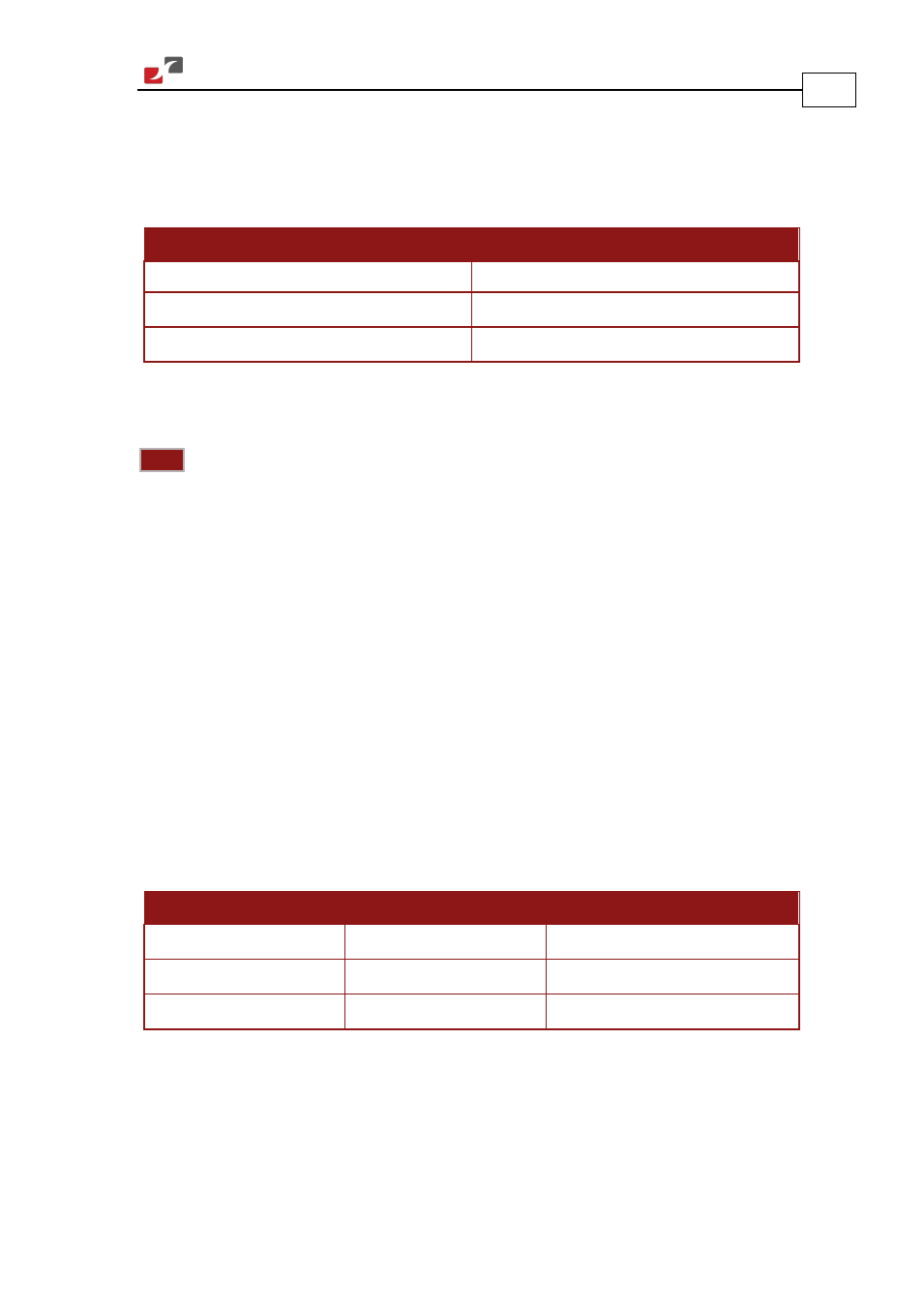
4.11. Communications
The communication interface may differ according to the user’s hardware. The Gold Trombone
can communicate using the following options:
Standard
EtherCAT
G-TRO
XXX
/
YYY
S
XX
G-TRO
XXX
/
YYY
E
XX
CAN
EtherCAT
USB 2.0
USB 2.0
Table 19: Gold Trombone Communication Options
For ease of setup and diagnostics of CAN communication, and CAN can be used simultaneously.
Note:
When the EtherCAT is connected, and FoE in operation, the USB cable connection
must be disconnected.
4.11.1. CAN Communication (J2)
In order to benefit from CAN communication, the user must have an understanding of the basic
programming and timing issues of a CAN network.
To connect the CAN communication cable:
1.
Connect the shield to the ground of the host (PC). Usually, this connection is soldered
internally inside the connector at the PC end. You can use the drain wire to facilitate
connection.
2.
Ensure that the shield of the cable is connected to the shield of the connector used for
communications. The drain wire can be used to facilitate the connection.
3.
Make sure to have a 120-Ohm resistor termination at each of the two ends of the network
cable.
4.
The Gold Trombone’s CAN port is non-isolated.
Pin (J2)
Signal
Function
31, 32
CAN_COMRET
CAN Communication Return
38
CAN_L
CAN_L bus line (dominant low)
40
CAN_H
CAN_H bus line (dominant high)
Table 20: CAN Pin Assignments