Main power, motor power and auxiliary power, Motor power – ElmoMC Gold Line Digital Servo Drives-Gold Trombone User Manual
Page 41
Gold Trombone Installation Guide (EtherCAT and CAN)
Installation
MAN-G-TROIG-EC (Ver. 1.604)
41
4.7. Main Power, Motor Power and Auxiliary Power
The Gold Trombone receives power from main and auxiliary supplies and delivers power to the
motor.
Note:
There are multiple voltage ratings of the Gold Trombone (80 V to 780 V), so you must
use the correct power supply according to the maximum operating voltage of the Gold
Trombone. See Section Chapter 3: Technical Information
4.7.1.
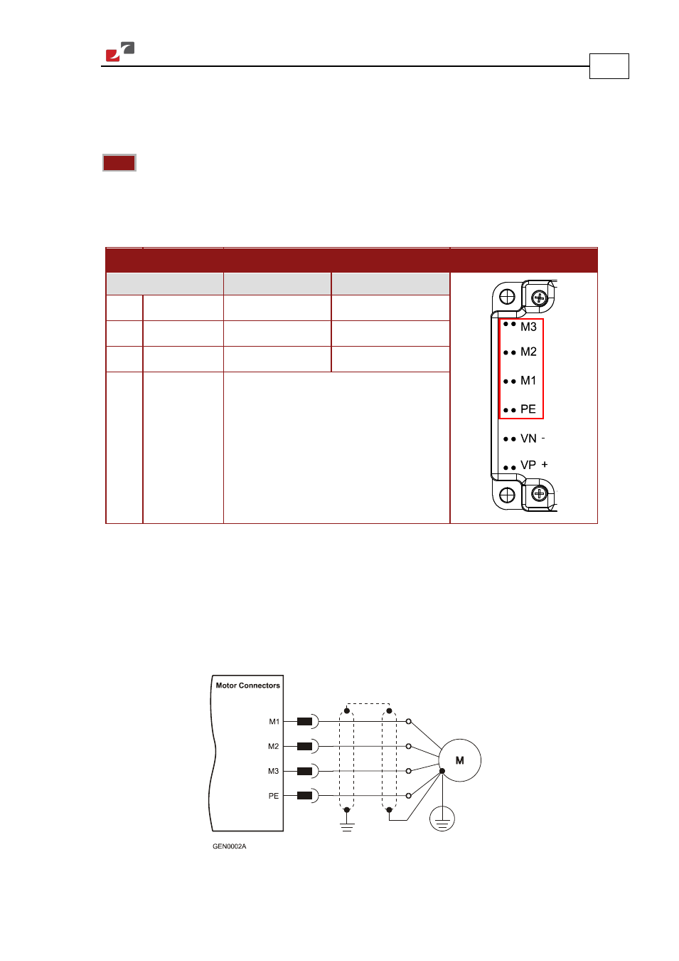
Motor Power
Pin Function
Cable
Pin Positions
Brushless Motor Brushed DC Motor
M3 Motor phase Motor
Motor
M2 Motor phase Motor
Motor
M1 Motor phase Motor
N/C
PE Protective
Earth
Power and Motor
Table 8: Connector for Motor
Connect the M1, M2, M3 and PE pins on the Gold Trombone in the manner described in
Section
4.5 (Integrating the Gold Trombone on a PCB). The phase connection is arbitrary as
Elmo Application Studio (EAS) will establish the proper commutation automatically during
setup. When tuning a number of drives, you can copy the setup file to the other drives and thus
avoid tuning each drive separately. In this case the motor-phase order must be the same as on
the first drive.
Figure 7: Brushless Motor Power Connection Diagram