Despatch MIC1162 Hi-limit User Manual
Page 27
23
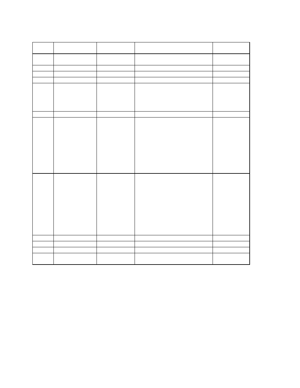
Table 6-1
Configuration Mode Parameters
STEP
DESCRIPTION
DISPLAY
CODE
AVAILABLE SETTINGS
FACTORY
SETTING
1
Input Range
Select
inPS
See App. C*
1420
2
Limit Action
ACt
Hi/Lo/Both
Hi
3
Limit Maximum
SPUL
+/- SPAN
Span max.
4
Limit Minimum
SPLL
+/- SPAN
Span min.
5
Alarm 1 Type
ALA1
nonE = No Alarm
P_hi = Process High
P_Lo = Process Low
LiHi = High Limit
LiLo = Low Limit
P_hi
6
Alarm 2 Type
ALA2
Same selection as ALA1
P_hi
7
Output 2 Usage
2
USE2
AL_d = Alm1 Direct
LA_r = Annunc. Reverse
LA_d = Annunc. Direct
Ad_r =Rev Logic AND
Ad_d=Dir Logic AND
Or_r =Rev Logic OR
Or_d=Dir Logic OR
A2_r = Alm Rev
A2_d = Alm Dir
Al_r = Alm1 Rev
Al_d
8
Output 3 Usage
2
USE3
Al-d =Alm Dir
rEcP = Rcdr Out P.V.
LA_r = Annunc. Reverse
LA_d = Annunc. Direct
Ad_r = Rev Logic AND
Ad_d = Dir Logic AND
Or_r = Rev Logic OR
Or _d = Dir Logic OR
A2_r = Alm2Rev
A2_d = Alm2Dir
Al_r = Alm Rev
Al_d (rEcP
when output 3
is retransmit)
9
Com Bit Rate
3
CbS
1200, 2400, 4800, 9600
4800
10
Com Parity
3
CPAr
nonE, EvEn, odd
nonE
11
Com Address
3
CAd
1 - 32
1
12
CJC Enable
CJC
EnAb
diSA
EnAb
1
Does not appear unless Output 3 is configured as 4-20 mA.
2
Does not appear unless additional output has been selected.
3
Does not appear unless communications option has been selected.
*The Hardware Definition Code and input jumper configuration may need to be
changed. See Appendices A and B.