Despatch MIC1162 Hi-limit User Manual
Page 14
10
2.4 Input Connections
In general, all wiring connections are made to the instrument after it is installed. Avoid
electrical shock. AC power wiring must not be connected to the source distribution
panel until all wiring connection procedures are completed.
FIGURE 2-7A
Main Supply
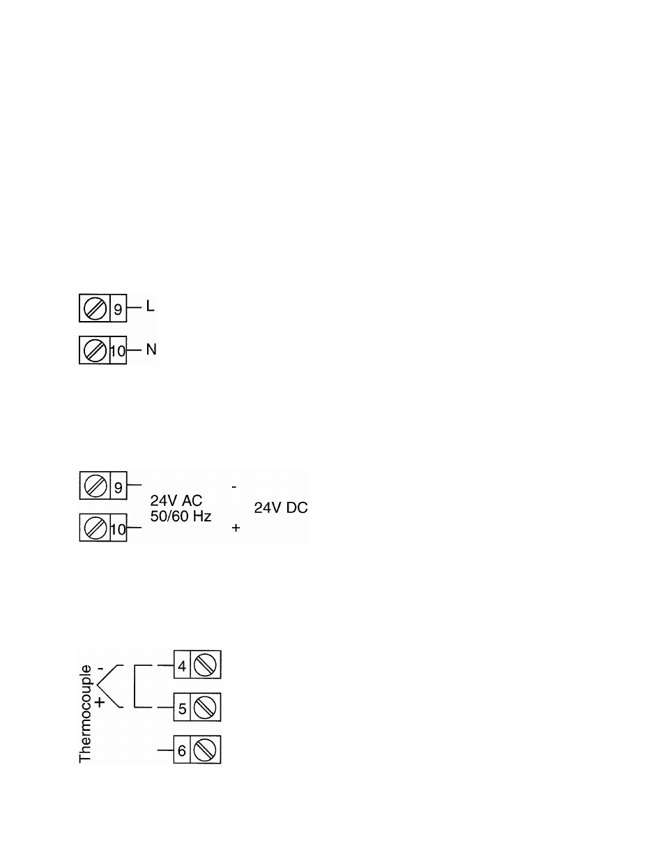
The instrument will operate on 90-264V AC 50/6OHz main supply. The power
consumption is approximately 4 VA. Connect the line voltage, hot and neutral, to
terminals 9 to 10 respectively as illustrated below.
FIGURE 2-7B
24V (Nominal) AC/DC Supply
The supply connections for the 24V AC/DC versions of the instrument are
shown below.
FIGURE 2-8
Thermocouple (T/C) Input
Make thermocouple connections as illustrated below. Connect the positive
leg of the thermocouple to terminal 5 and the negative leg to terminal 4.
FIGURE 2-9