COATS 5035 A/E Tire Changer User Manual
Page 12
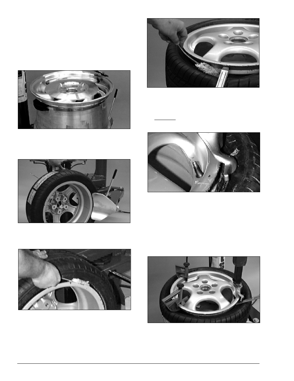
NOTE: Some wheels have a low pressure
sensor/transmitter strapped to the wheel. This is
especially true on run-flat tire/wheel systems. The
sensor is positioned directly opposite from the valve
stem. To avoid damaging the sensor, always loosen
the top bead at the valve stem first, then loosen the
bottom bead at the valve stem, and then continue to
loosen the remaining circumference of the beads as
necessary (Figure 20).
Figure 20 - Wheel with Low Pressure Sensor/Transmitter
3.
Loosen bottom bead, starting with valve stem
positioned directly next to the loosener shoe
(Figure 21).
Figure 21 - Loosen Bottom Bead
4.
Liberally lubricate the bottom bead of the tire
(Figure 22).
Figure 22 - Lubricate Bottom Bead
5.
Clamp the wheel to the table top as described in
item B on page 9. Always clamp custom wheels
from the outside.
6.
Lubricate upper bead liberally. Use the bead
lifting tool to help push the tire bead down so the
bead area is easier to reach.
Figure 23 - Lubricate Upper Bead
7.
Move swing arm into place and adjust as
described on page 4, steps 7, 8, and 9. Increase the
distance between the demount head and the wheel
an additional 1/16 to 1/8 inch with the adjustment
knob. Locate the valve stem directly under the
demount tool before proceeding.
Figure 24 - Position Valve Stem Under Demount Head
8.
Insert bead lifting tool between knob on
demount tool and tire bead. Pull lifting tool down
over wheel to lift bead up and over the knob.
NOTE: On asymmetrical hump wheels and stiff
sidewall performance tires, it may be necessary
to use 2 optional drop center tools (part
#435685) to hold tire in the drop center so that
the bead can be lifted over the demount tool.
Figure 25 - Insert Bead Lifting Tool (Optional Drop Center
Tools Shown)
9.
Hold lifting tool in place and depress the table
top control pedal momentarily to jog the wheel a
short distance.
10 • 5035 A/E Rim Clamp Tire Changer