COATS Kit 8110584, Pressure Limiter User Manual
Page 2
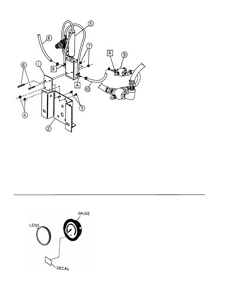
RC-20A and 20AA Pressure Limiter:
1. Remove the side panel.
2. Mount pressure limiter bracket (ref 1) to inflation
bracket (ref 2) using two 1/4-inch bolts 3/4-inch long (ref
3) and two 1/4-inch nuts (ref 4) provided in kit. Tighten
securely.
3. Install pressure limiter (ref 5) to pressure limiter
bracket (ref 1) using two 1/4-inch bolts, 1-3/4-inch long
(ref 6) and two nuts (ref 7) provided in kit. Fasten
securely.
4. Remove 1/4-inch hose (ref 8) from small valve (ref
9) and connect to port B on pressure limiter (ref 5).
5. Connect 1/4-inch hose 20-inches long (ref 10) sup-
plied in kit to port A on small valve (ref 9) and port A on
pressure limiter (ref 5). Securely tighten using 1/4-inch
hose clamps provided in kit.
6. Check all connections for proper instal-
lation and tightness prior to recon-
necting air supply.
7. Check unit for proper opera-
tion. Refer to the pressure limiter
maintenance section on page 4 of
this instruction.
8. Remove lens cover from air
gauge and install new decal to gauge
as shown in diagram. Reinstall lens
cover.
9. Replace side panel.
10. Review proper technique and operation with the
operators and supervisors.
8110585 01 2 of 4
40-40 Pressure Limiter:
1. Remove the operator’s side panel from the
machine.
2. Remove front side panel support from chassis by
removing two 3/8-inch self tapping screws. Install new
bracket (ref 1) in same location using the two 3/8-inch
self tapping screws just removed. Tighten securely.
3. Install pressure limiter (ref 2) to pressure limiter
bracket (ref 1) using two 1/4-20 x 1-1/2-inch long bolts
(ref 3) and two 1/4-20 lock nuts (ref 4) provided. Fasten
securely.
4. Disconnect quick coupler. Remove quick coupler
end from 1/4-inch hose (ref 7). Attach 1/4-inch hose (ref
7) to pressure limiter port A. Sercurely fasten all
clamps.