COATS CDH-9043 Electric-Hydraulic Tire Changer User Manual
Page 10
10
First use handle (15, Fig. D) to tip the arm to this position.
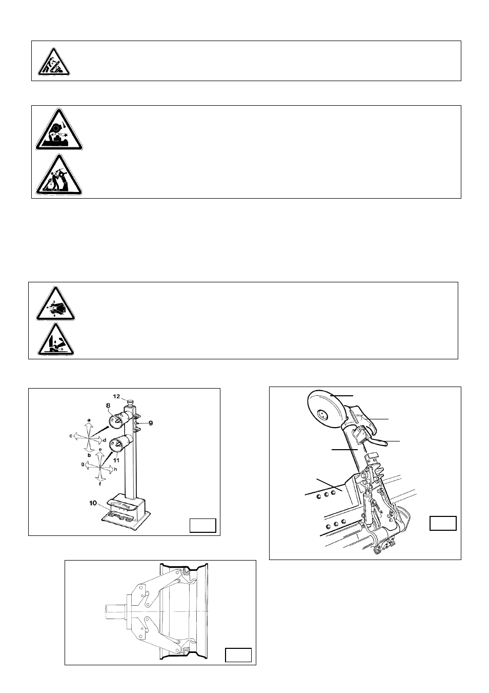
1) Move the joystick (8, Fig. C) up (a): the spindle carrier arm (2, Fig. A) should lift; move the joystick down (b): the arm should lower.
Move the joystick towards the left (c): the tool carriage and the mobile platform (13, Fig. D) should move towards the spindle (3, Fig. A);
move the joystick towards the right (d) the carriage and platform should move away from the spindle.
2) Turn switch lever (9, Fig. C) towards the top: the spindle arms (3, Fig. A) should open; move the lever down and the spindle arms should
close.
3) Push the lever (11, fig. C) upwards (e) to have the tool arm (14, fig. D) released and tilted outwards; push the lever
downwards (f) to have the tool arm hooked in working position. Push the lever rightwards (h) to have the tool carriage
moved rightwards; push it leftwards to have the tool carriage moved to the opposite side.
4) Depress the right pedal (10, Fig. C): the spindle (3, Fig. A) should turn clockwise; depress the left pedal: the spindle should turn anti-
clockwise.
CAUTION!
Do not move your face close to the tool carrier arm when you release it to tip it as needed.
DANGER!
When the spindle carrier arm is lowered, there is always a potential for crushing anything in its
movement range. Always work from the position given in the instructions keep well out of the working
range of the various moving arms.
DANGER!
When the spindle arms open or closed, there is always a potential for crushing anything in their movement
range. Always work from the position given in the instructions keep well out of the spindle’s working
range.
D
C
E/1
18
17
1
1
15