COATS Vero Series Wheel Balancer User Manual
Page 15
Important: Always read and follow instructions.
• 9
3.
Rotate the laser locator knob to position the laser
locator dot at the desired weight location. See figures
10 & 9B.
Note: For best performance, choose a weight position
outboard as far inward (in the rim) as wheel allows.
4.
Enter the A & D wheel measurements, wait for
BEEP. Then, before returning arm to home position,
move arm to inner area of wheel and position the line
laser beam at the T2 Tape laser locator dot position; wait
for BEEP.
5.
Lower hood; wheel spins.
6.
When the inboard unbalance is displayed, the
inboard center bar highlights green. Attach inboard cor-
rective weight at top-dead-center.
Note: If an inboard corrective weight is not required
then the wheel will stop at the outboard corrective
weight location.
7.
Press NEXT to rotate wheel to outboard corrective
weight location where the outboard center bar is steady
and the two bars on either side blink.
Note: The laser locator dot will stop blinking.
8.
Center and attach the outboard corrective weight
at laser locator dot location as shown in figure 13.
9.
Respin tire/wheel to check balance.
Figure 13 - Centering Corrective Hidden Weight At Laser Loca-
tor Dot Location
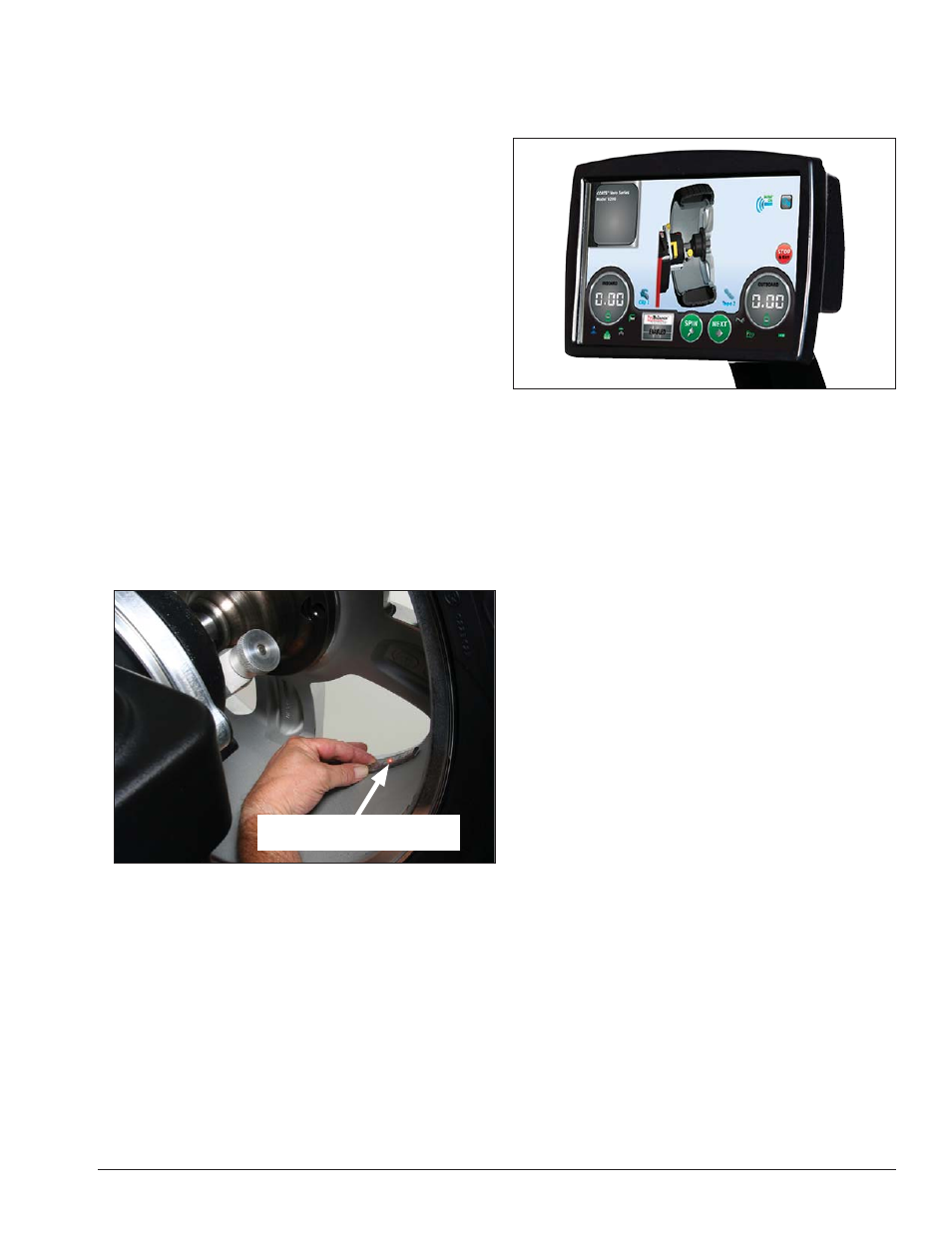
Touchscreen
The balancer touchscreen is a resistive touch panel
(figure 14). To enter a function, press the appropriate
function icon.
Figure 14 - Press Touchscreen Functions
Note: Only press the touchscreen with your fingers.
Never use the weight hammer or other pointed objects
to press on the screen.
Center Corrective Weight At
Laser Locator Dot Location