COATS Vero Series Calibration User Manual
COATS Equipment
COATS, Inc. • Hennessy Industries • 1601 J.P. Hennessy Drive, LaVergne, TN 37086
(800) 688-6359 • (615) 641-7533 • (615) 641-5104 FAX • www.ammcoats.com
85609633 00 06/14
© COPYRIGHT 2014 ALL RIGHTS RESERVED PRINTED IN U.S.A.
Calibration Wheel Set Up
For best calibration results, use a 16-inch steel tire/
wheel assembly on the balancer. A balanced tire/wheel
assembly is required.
What is needed:
• 16-inch steel wheel in good condition
• 16-inch tire in good condition
• Tape Weights
Note: To make calibration easier, use tape weights
and place them at the Tape 1 (T1) and Tape 2 (T2)
positions on the steel wheel. This keeps the flange
positions free for placement of the 4-ounce calibration
weight.
Helpful Hint: Take a paint pen and mark the tire as
shown in the provided photo. The mark should be as
accurate as possible — from Inboard to Outboard. Posi-
tion on the wheel does not matter as long as the marks
match at the same location on each side of the wheel.
If you have marked the wheel (as noted above), follow
this procedure to make the 4-ounce calibration weight
placement easy and accurate.
1.
Turn the machine OFF. Mount tire/wheel assembly
on the balancer and rotate the wheel so that the marks
you just added are at the 12 o’clock position. Hold the
wheel in this position and turn the balancer ON. The
balancer will be indexed to this wheel position for cali-
bration and weight placement.
Machine Calibration
1.
Press SETTINGS icon and then select MACHINE
CALIBRATION.
2.
Press continue.
3.
Enter the D dimension (include decimal point,
example: 16.0 for a 16-inch wheel). Press ENTER.
4.
Lower the hood and press SPIN.
5.
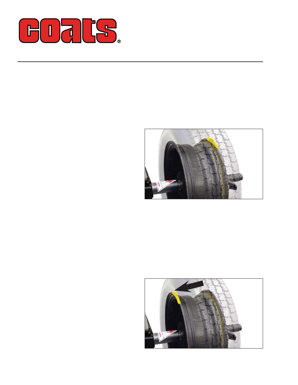
After spin, raise the hood. Attach 4-ounce calibra-
tion weight to the outside flange at top-dead-center.
Figure 1 - Calibration Weight On Outside Flange At Top-Dead-
Center
6.
Lower the hood and press SPIN
Important: It is critical that the inner weight be
placed accurately to achieve proper calibration. If the
calibration weight is not moved from the outside flange
directly across to the inside flange, an inner weight
placement error will occur. To correct, follow the bal-
ancer instructions.
7.
After spin, raise the hood. Move the 4-ounce
calibration weight directly across and attach it on the
inside flange at top-dead-center.
Figure 2 - Calibration Weight Moved (Directly Across) To
Inside Flange
Vero Series™ Wheel Balancer
Calibration Instructions