Start-up & operation, Service & troubleshooting – Carlin 301CRD User Manual
Page 19
Model 201CRD & 301CRD 240-VAC Advanced oil burners — Instruction manual
Carlin part number MN2301A Rev. 10/21/10
– 19 –
Start-up & operation
Do not start the burner if the combustion chamber contains oil or
oil vapor.
Per UL requirements, the control will not turn on if the cad cell
senses fl ame during the self-test. If the cad cell sees light, the
control will remain in self-test mode until the cad cell no longer
senses light (fl ame). The amber LED will remain on, but blink off
momentarily
every 3 to 4 seconds.
Check 60240 control label for trial for ignition (TFI), pre-purge
and post-purge timings.
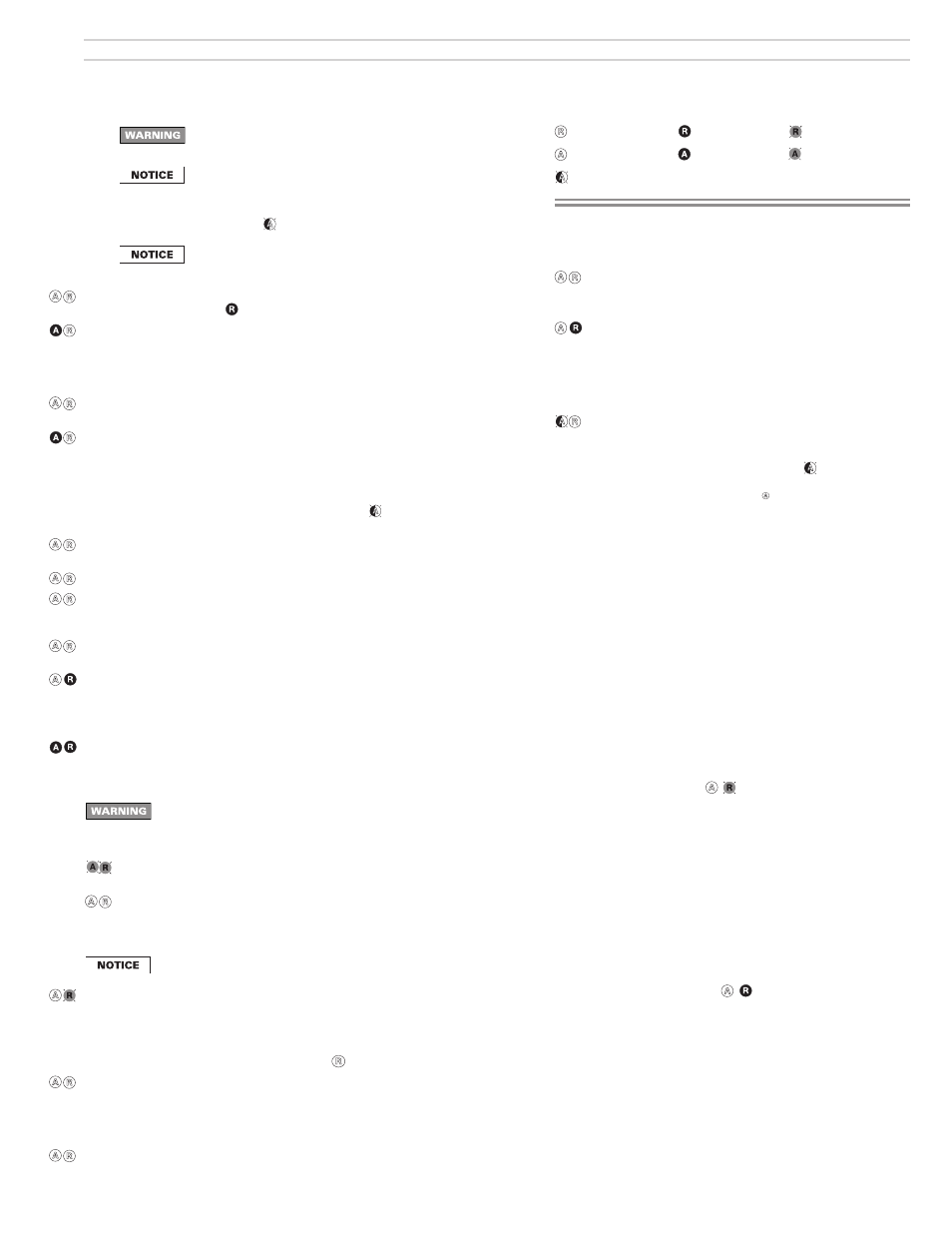
Model 60240 diagnostic LED’s
– Red OFF
– Red ON
– Red FLASHING
– Amber OFF – Amber ON – Amber FLASHING
– Amber BLINKING
(blinks off momentarily every 3 to 4 seconds)
Service & Troubleshooting
Burner (control) will not come on
No power to control
• Check line voltage to the control (at least 102
VAC
).
• Check all electrical connections.
Control is in lockout
• Red LED will be on. Press the reset button for
1 second.
• If the control returns immediately to lockout, the
Safety Monitoring Circuit may have detected an
internal control problem. Replace the control.
CAD cell seeing light
• Amber LED blinks off each 3 to 4 seconds. Remove
one yellow lead from FF terminal on the control.
If the amber LED remains on with a wire de-
tached, the control is defective.
If
amber
LED goes off , control is OK, and:
• light is leaking into the burner housing,
OR
• CAD cell is defective,
OR
• there is a problem with the CAD cell wiring or
holder.
• If appliance was recently shut down, CAD cell
may see residual hot spots in chamber.
To
troubleshoot:
• Check CAD cell by unplugging it and measur-
ing the resistance across its pins: dark resis-
tance at least 50
KOHMS
; room light resistance
less than 10
KOHMS
. Replace if necessary. If
the CAD cell functions properly, reinstall the
cell and close the burner housing.
• Check for stray light by measuring the CAD
cell resistance looking into the inactive com-
bustion chamber. It should read at least 50
KOHMS
.
Repeated fl ame failures ( fl ashing red LED)
Check
for:
• CAD cell is defective.
• Air leaking into oil line causing fl ame out — Check oil
line connections and fi lter gasket.
• Defective nozzle causing flame to be erratic —
Change nozzle.
•
Excessive
airfl ow or draft causing fl ame to leave
burner head — Check for proper air shutter setting
and draft.
• Excessive back pressure causing fl ame to be erratic
— Check appliance and fl ue for sooting/plugging.
Control locks out after TFI ( red LED on)
Check
for:
• No oil to burner — Check oil supply, fi lter, lines.
• Shorted electrodes — Inspect for cracked porcelain
and replace as needed.
• Poor spark — Check electrode spacing and condition
per burner manual. Replace or realign if necessary.
• Nozzle clogged — Replace nozzle.
•
Airfl ow too high — Check air shutter setting.
• Ignitor module defective — Replace if no spark.
• CAD cell defective.
• Oil valve stuck in closed position.
• Check wiring connections.
Power ON
Open all manual oil line valves. Close the line switch. (If Red LED turns
on constant
, control is in lockout. See below to reset.)
Self-test 1
The control performs a “boot-up” test to verify internal operation each
time power is applied to the red/white wire. About 4 seconds after
power application, the amber LED turns on. The test continues for
about 6 more seconds. If the test fails, the control turns the amber LED
off and repeats this test sequence until successful.
Stand-by
(No call for heat) If Self-test 1 is successful, amber LED turns off and
control waits for heat call.
Call for heat Set thermostat (or limit) to call for heat. Thermostat circuit must be
closed and power coming to black wire from limit circuit.
Self-test 2
The amber LED turns on. For the fi rst 3 to 4 seconds, the control per-
forms a self-test. If the cad cell senses fl ame, the control repeats this
test until fl ame is no longer detected. During this time, the amber LED
will remain on, but blink off momentarily
every 3 to 4 seconds. If the
control detects motor contacts closed, lockout occurs.
Burner on
After the self-test, amber LED turns off. The ignitor starts, followed 1
second later by the motor.
Pre-purge The
oil valve opens after the valve delay-on period (pre-purge).
TFI
The cad cell must sense fl ame within the TFI time limit (trial for ignition).
After cad cell senses fl ame, the ignitor stays on another 10 seconds
(fl ame stabilization period).
Run
The burner continues fi ring during call for heat if the cad cell senses
fl ame. Both LED’s are off during normal running.
Lockout
If cad cell does not sense fl ame within the TFI time limit after burner
starts, lockout occurs. The control turns the red LED on constant, and
closes the alarm contact.
To
Reset
Push in and hold reset button for 1 second, then release.
Latch-up
If the control locks out 3 times during a single call for heat, latch-up
occurs. The control turns on both the amber and red LED’s constant.
You must use the special procedure below to reset the control after
latch-up.
Reset after latch-up — Only a qualifi ed service technician should
attempt to reset the control after latch-up. The problem that
caused the repeated burner problems must be corrected before
returning the burner to normal operation.
Push in and hold the reset button for about 10 seconds. The amber and
red LED’s will begin to fl ash alternately.
After the LED’s begin fl ashing, continue holding the reset button for
about another 20 seconds. The LED’s will turn off. Release the reset
button and the control will restart. (Releasing the button before the
LED’s turn off will cause the control to remain in latch-up.)
The 60240 control will not reset from lockout or latch-up if power is
interrupted.
Flame failure If the cad cell loses fl ame signal during operation (after the TFI), the
red LED fl ashes. The oil valve closes within 2 seconds. The motor re-
mains on for the motor delay off period, then shuts off. (If no oil valve is
wired to the control, the burner shuts down within 2 seconds.) Recycle:
Control waits for 65 seconds (with red LED fl ashing), then begins again
at Self-test 2. Red LED goes off
.
Post-purge Set thermostat (or aquastat) to stop call for heat. The oil valve (if
installed) will turn off within 2 seconds. The motor remains on for the
motor delay off period (post-purge), then turns off. (If no oil valve is
wired to the control, the burner shuts off within 2 seconds after end of
call for heat. There is no post-purge.)
Stand-by
Control remains in stand-by mode until limit circuit sends power to the
black wire and thermostat circuit closes (call for heat).