Removing/installing head assembly, Prepare burner – Carlin 301CRD User Manual
Page 10
Model 201CRD & 301CRD 240-VAC Advanced oil burners — Instruction manual
Carlin part number MN2301A Rev. 10/21/10
– 10 –
Removing/installing head assembly
Use care when handling burner components after the burner
has been fi ring. Components can be hot and could cause
severe personal injury.
Removing the combustion head assembly
You will need to remove the combustion head assembly for inspection of
the assembly, replacement of the oil nozzle or adjustment of electrodes.
To remove the assembly:
1. Loosen the screw on the left side of the burner housing that secures the
ignitor plate in place. Swing the ignitor plate open.
2. See Figure 7.
3. Unscrew the oil line fi tting from the elbow at the end of the oil tube.
4. Remove the combustion head assembly by pulling the assembly up and
out of the housing.
7. Handle the assembly with care to avoid bending or moving the electrodes,
or damaging the electrode ceramic insulators.
8. Inspect the gasket on the bottom of the ignitor plate. The gasket prevents
air from escaping from the housing. Replace the gasket if not in good
condition.
9. Inspect the ignitor contact clips. Clean or replace if necessary to ensure
reliable contact with the electrodes.
Replacing the combustion head assembly
To replace the combustion head assembly, reverse the sequence above.
• Make sure the oil line bracket seats into the slot on the adjusting screw.
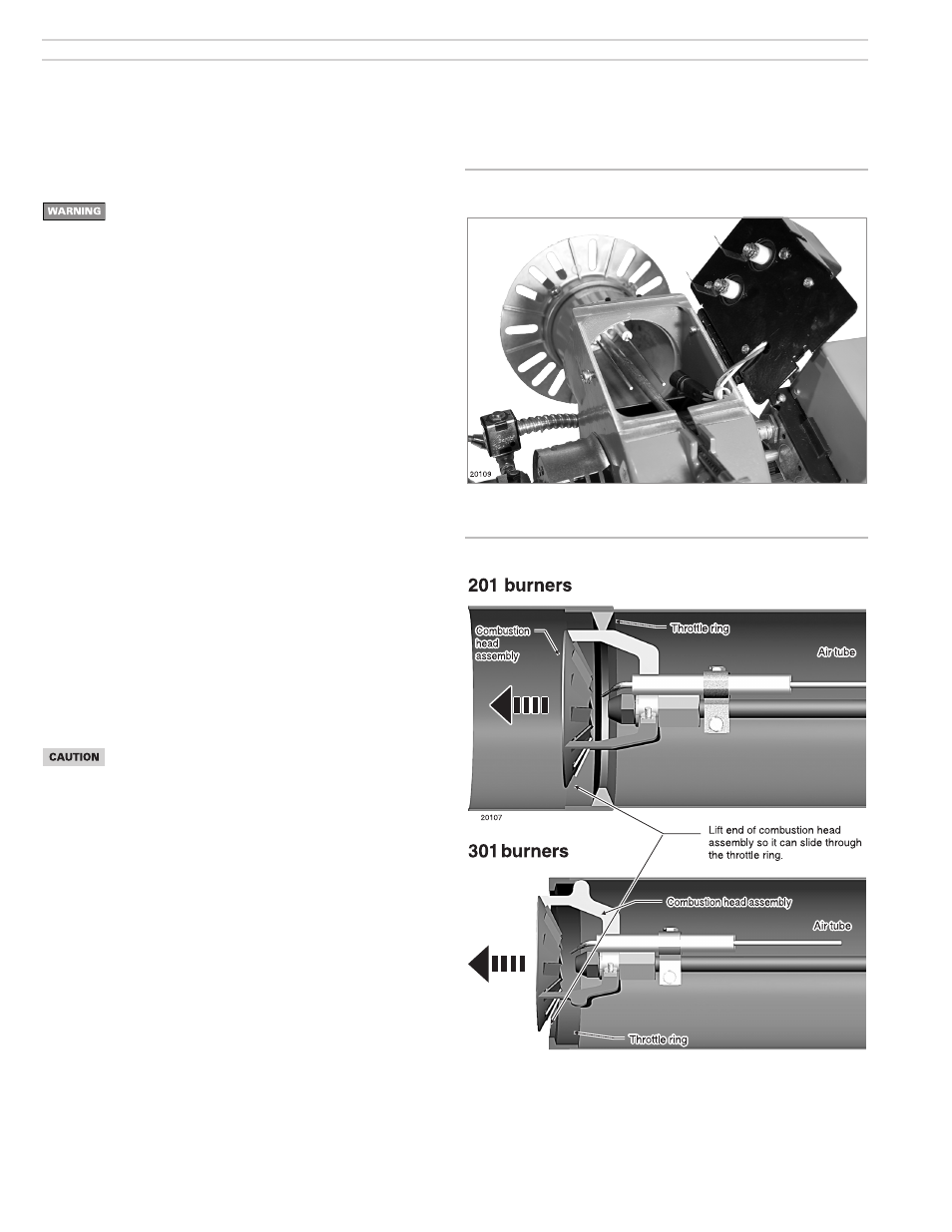
• See Figure 8. You will have to lift the end of the assembly to guide it through
the throttle ring or air cone at the end of the air tube. DO NOT FORCE.
Use care when tightening the oil line fi tting to oil tube extension.
Tighten securely, but do not cross-thread or over-tighten.
Figure 8 Inserting combustion head assembly
Figure 7 Removing/inserting combustion head assembly
3. Prepare burner