Set initial burner air settings, Prepare burner – Carlin 301CRD User Manual
Page 12
Model 201CRD & 301CRD 240-VAC Advanced oil burners — Instruction manual
Carlin part number MN2301A Rev. 10/21/10
– 12 –
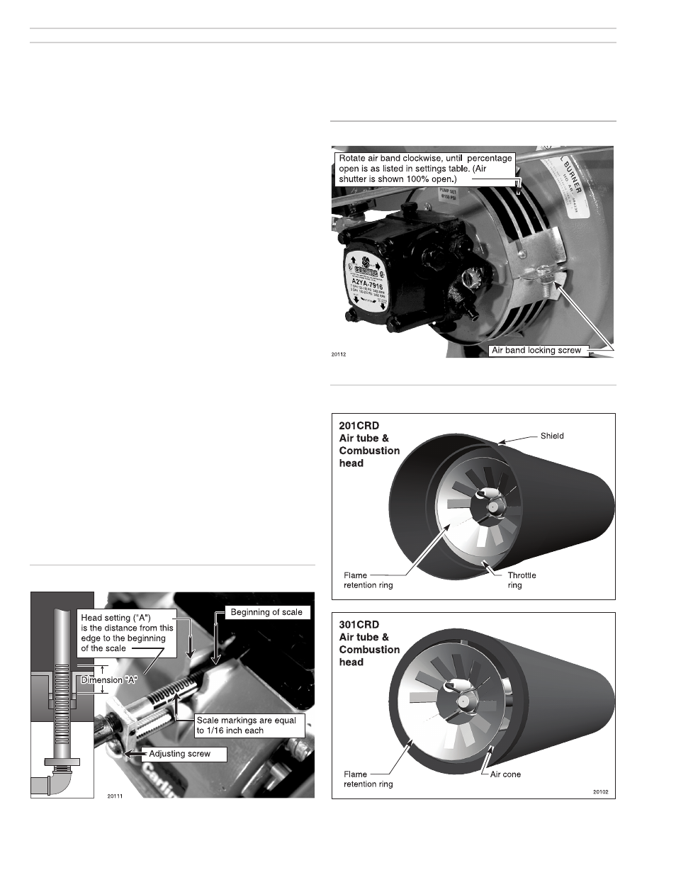
Figure 13 Combustion head/air tube combinations, typical
Set initial burner air settings
Combustion head (“A” dimension)
1. The combustion head adjusting screw is used to set the spacing between
the retention ring and throttle ring (or air cone), regulating how much air
passes around the retention ring.
2. See Figure 11.
3. Rotate the head adjusting screw until the distance from the housing detent
to the beginning of the scale equals the value given in Table 4, page 13
(“A” dimension).
Air band
1. See Figure 12. Loosen the air band locking screw and rotate the air band
until the opening equals the percent opening given in Table 4, page 13.
Final adjustments
1. The burner is now adjusted to the approximate air settings for the fi ring
rate chosen.
2. When you check combustion with instruments during start-up or servicing,
you may have to adjust the head and/or air band slightly to achieve the
desired effi ciency.
• Increase the combustion head setting (“A” dimension) to increase air. If
additional adjustment is needed, open the air band slightly.
• Decrease the combustion head setting (“A” dimension) to decrease air. If
additional adjustment is needed, close the air band slightly.
3. See “Adjust burner using test instruments,” page 20.
4. Note that positive pressure overfi re will reduce air fl ow, requiring more air
opening.
Figure 11 Combustion head setting
Figure 12
Air band setting
3. Prepare burner
(continued)