Step 4, Step 5, Step 6 – B&W Trailer Hitches 1208R User Manual
Page 3
After cutting the notches the rear cross member can be installed using the
two notches to accept the legs of the cross members. The rear crossmember
can be identified as the 2” x 2” angle with two cut outs on one of the legs.
Slide the angle across the top of the frame using the two notches to accept
the legs of the crossmember with the leg containing the two cut outs toward
the front of the truck. Center the cross member on the top of the frame. Next
turn the crossmember so that the two cut outs are toward the bed floor and
the crossmember leg that contains the holes will lay flat on top of the frame.
Next install the pin brackets on each side of the cross member. The mounting
kit contains a driver side and passenger side pin bracket. The driver’s side
can be identified by having a notch cut in it for clearance of a fuel canister
tube on some models. When they are installed correctly the pin will be in the
hole on the inside of the frame and the bolt holes will face up and forward and
align with the two outside holes on each end of the rear cross member. Place
a ½” x 1 ½” bolt with a lock washer and nut in the four holes that bolt the pin
brackets to the rear cross member.
Do not fully tighten at this time.
STEP 4
INSTALL CENTER SECTION
Install the center section by raising it up between the frame on the passenger side
of the truck and the exhaust pipe. At the same time turn it flat and slide it over
the gas tank, making sure that the spring loaded latch pin assembly is toward the
driver’s side of the truck. With the center section in the center of the truck slide it
toward the rear placing the flat part of the center section that has 4 slotted holes
in it between the bed cross member and the round frame cross member. Slide it
back until the slotted holes align with the holes in the rear cross member. Install a
½” x 1 ½” bolt through the rear cross member and the slotted holes in the center
section and place a flat washer, lock washer and nut on the bolts.
Do not fully tighten at this time.
STEP 5
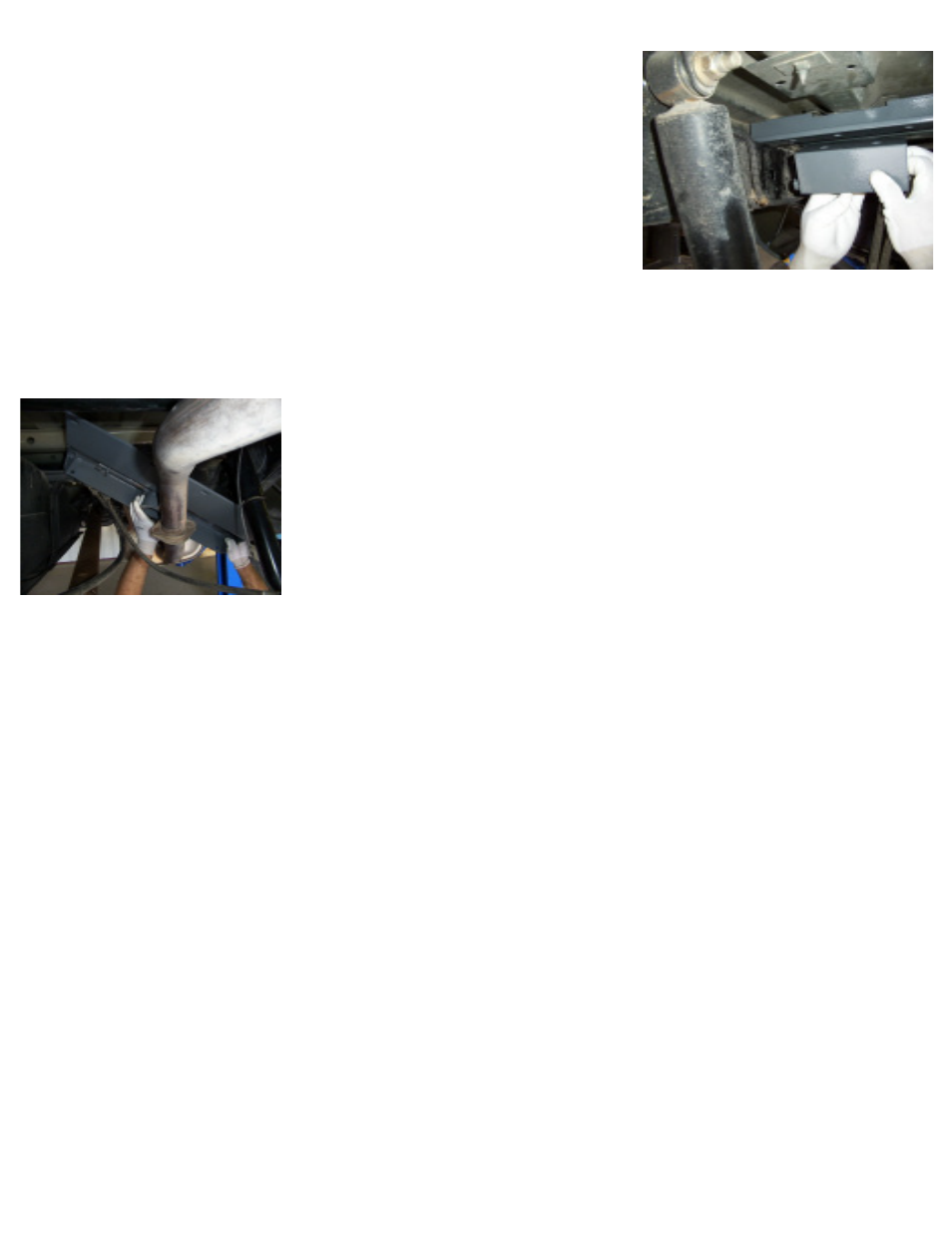
INSTALL FRONT CROSS MEMBER AND BRACE
Install the cross member brace between the frame and truck bed from the driver’s side. The cut out area should be
facing down and toward the driver’s side. This will allow clearance for the fuel tank on some models. Slide it back
toward the center section. Next install the front cross member. Slide the end with the short notch between the frame
and truck bed from the driver’s side. The notch should be facing up and toward the front of the truck. This will allow
clearance around the shock bracket on the passenger side when fully installed. With the cross member and brace
spanning the frame slide both back against the center section. Install a ½”x2” carriage bolt through the cross member
and brace on the passenger side just behind the shock bracket. This will be used later.
While pushing up on the center section (so the socket top fits through the four inch hole in the truck bed) align the
holes and install the carriage bolts through the cross member, brace and then the center section. Place a flat washer,
lock washer, and nut on each bolt. Do not fully tighten at this time.
STEP 6
INSTALL SIDEPLATES
Before the passenger side sideplate can be installed a wiring harness must be moved. This can be done by pulling the
two push in connectors out of the frame directly under the shock bracket on the outside of the frame. Lift the harness
up and over the front cross member. The sideplate when installed will hold it in this location.
The side plate with the decal goes on the driver’s side. Place it against the frame with the bent ear with the slotted
hole facing inward just behind the cross members. Place a carriage bolt through the cross member, brace and the side
plate ear secure with a flat washer, lock washer, and nut. The bottom of the sideplate should face in and match the
slope of the under side of the frame when installed properly. Place one of the bolt guide assemblies (bolt first) through
the larger oval hole just in front of the sideplate, twisting it around and back out through the smaller hole in the frame
and sideplate. Use the tab on the end of the bolt guide assembly to hold in place while a 5/8” flange nut is installed.
Repeat this on the passenger side. The passenger side sideplate may not lay perfectly flat against the frame because
of the shock bracket that is welded on. This will cause no problems with the fit or function of the hitch.