Installation instructions, Ball location - 46 ½” all beds, Step 1 – B&W Trailer Hitches 1208R User Manual
Page 2: Step 2, Step 3
INSTALLATION INSTRUCTIONS
STEP 1
REMOVE SPARE TIRE, HEAT SHIELD, FUEL VALVE CANISTER, AND INNER FENDER GUARDS
A) The heat shied under the bed floor must be removed before the hitch can be installed.
This is done by removing the eight screws that hold the heat shield to the bed cross members
using a 10 mm. wrench, then slide the heat shield toward the rear of the truck and remove.
The heat shield can be discarded, the hitch will replace this section of the heat shield.
B) Using a small screwdriver remove the vent hose from the bed cross member. Locate the
rectangle shaped fuel valve canister. If it is mounted behind the tube frame cross member it
will not interfere with the installation. If it is mounted if front of the tube frame cross member
it will need to be lowered during the installation. First remove the 3 small bolts that hold the
canister bracket to the truck using a 10 mm. wrench. Then slide the canister toward the center
of the truck far enough to allow the
end toward the frame to be pulled downward. Then slide
the canister back toward the frame to allow the complete canister to drop down about 4 to 5
inches this will be enough room to complete the installation.
STEP 2
MARKING AND CUTTING THE 4 INCH HOLE
BALL LOCATION - 46 ½” ALL BEDS
Measure from the back end ( tail gate end) of the truck bed floor by hooking a tape
measure over the end of the bed and marking the floor at 46 ½”. Using a tape mea-
sure find the center of the bed floor between the fender wheel wells,this will be the
center point of the 4 inch hole.
These locations are critical for the correct installation of this hitch, so measure, mark,
and saw carefully. Make a 4” hole in this location using a 4” hole saw, or by marking
a 4” circle and cutting it out with a saber saw equipped with a metal cutting blade.
STEP 3
INSTALL REAR CROSSMEMBER AND PIN BRACKETS
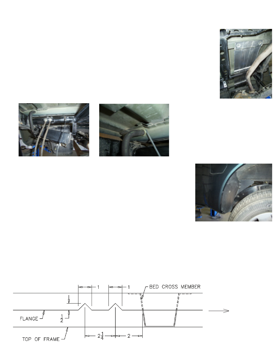
Before the rear cross member can be installed there must be two small notches cut in the bed floor flange behind the
center bed cross member on the passenger side. At 2” behind the center cross member make the first V-shape notch
½” tall x 1” wide in the bed floor flange. The second notch will need to be 2 ¼” behind the first.
(see diagram)
Front of Truck
C) The inner fender guards toward the front
of both rear fender wells will need to be re-
moved to allow the installation of the hitch
side plates. This is done by removing two
screws and sliding the guard toward the tire.
These guards will be replaced in step 10.