Before installing, Installation instructions – B&W Trailer Hitches 1251R User Manual
Page 2
BEFORE INSTALLING
OVERHEAD LIFTING DEVICE
WARNING
Most trucks have FUEL LINES and/or BRAKE LINES and/or ELECTRICAL WIRES located along the frame
rails where B&W Turnoverball™ hitches install. Carefully examine the location of fuel lines, brake lines and
electrical wires BEFORE INSTALLATION. Be certain you will not damage fuel lines, brake lines or electrical
wires when positioning hitch components, drilling holes, tightening fasteners, and lifting and lowering the
truck bed. The fuel tank vent, located on top of the gas tank, can be easily damaged during the instal-
lation of the hitch components. Care must be taken when positioning the front crossmember and center
section components.
Warning
On Short bed trucks, BEFORE INSTALLING THIS HITCH, check for adequate turning clearance between the
front of all of your trailers and the truck cab.
Warning
DO NOT invert the ball in the socket when carrying heavy loads on 2 wheel drive trucks. The ball may hit
the top of the differential. Remove the ball from the socket before loading. A plug for the socket is avail-
able from B & W.
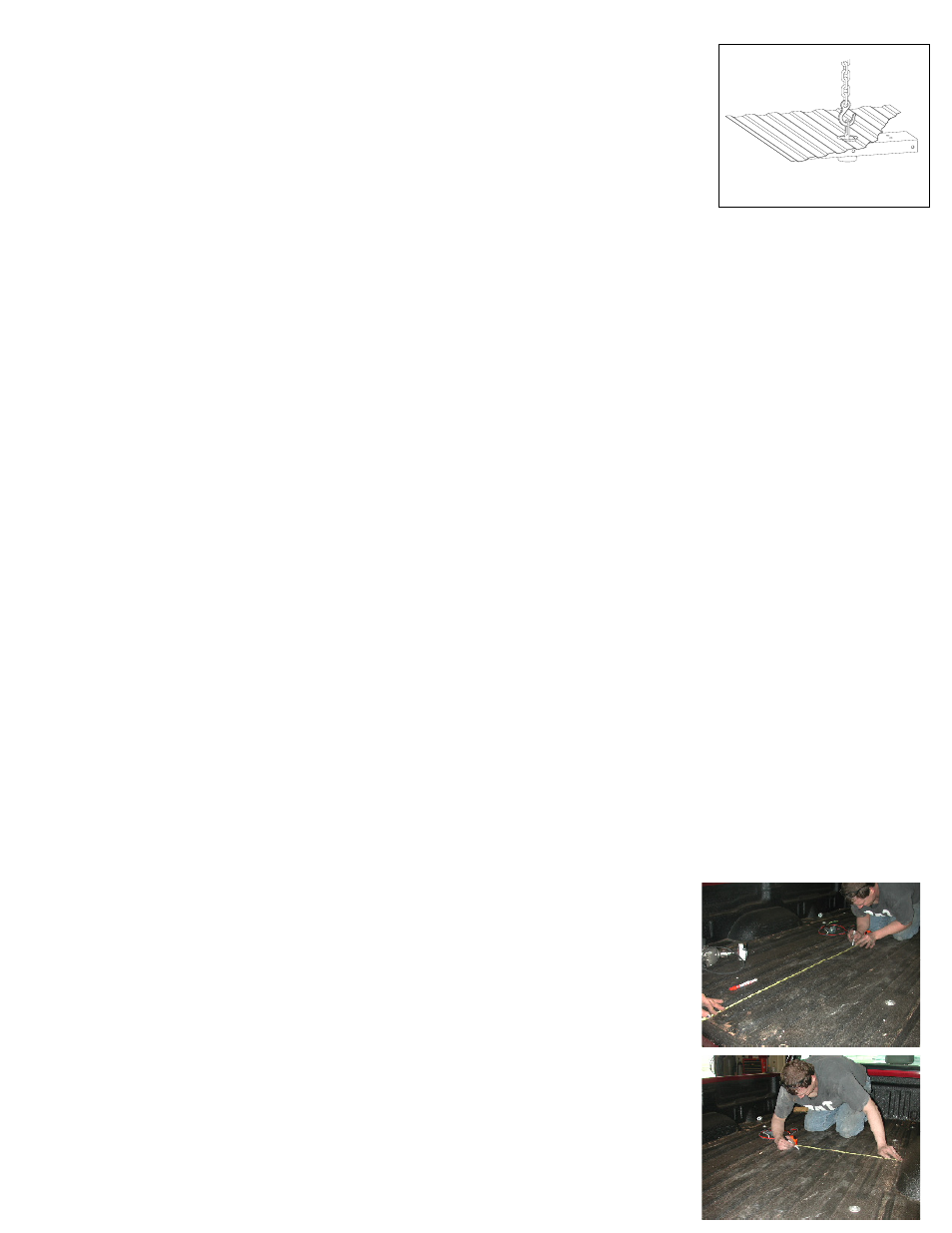
An overhead-lifting device, such as chain falls, engine hoist, or cable come-a-long,
can be used to lift the center section of the hitch in place. Lower a loop of rope
or chain through the 4” hole in the truck bed floor and attach it to the latch pin
in the round hitch receiver tube in the center section. Use the lifting device to
raise the center section until the round hitch receiver tube that protrudes from
the center section fits in the 4” hole in the truck bed floor. Maintaining upward
pressure may facilitate fastening the crossmember to the center section, es-
pecially if the truck bed floor has been distorted downward from heavy use. If you use an overhead-lifting
device, it should be disconnected before squaring the center section across the frame, installing the side-
plates and torquing fasteners.
INSTALLATION INSTRUCTIONS
General Information
The Toyota Tundra truck has two bed cross members about six inches apart over the rear axle. A special
center section has been developed to fit between these two bed cross members. The center section is formed
to allow the Turnoverball™ cross bars to be located in front of and behind the bed cross members. Because
the center section fits so closely between the cross members, it is very important that the 4” hole in the
truck bed floor be carefully measured and precisely located. This hitch
also utilizes side plates that attach to the inside of the truck frame rails, rather
than the outsides of the frame as do other Turnoverball™ hitches.
STEP ONE
Begin by verifying and measuring the correct hole location in the truck bed
floor. Measure from the back end (tail gate end) of the truck bed floor by hook-
ing a tape measure over the back of the sheet metal and marking the floor at
the 46 1/4”. Center the measurement between the fender wheel wells. This
location is critical to the correct installation of this hitch, so measure, mark and
saw carefully. If the truck has a plastic bed liner, you may drill through both,
but it is more difficult to accurately locate the midpoint between the fender
wheel wells, and to be sure that the bed liner does not move while sawing the
hole. Make a four-inch hole at this location using a four-inch hole saw, or by
marking a four-inch circle and cutting it out with a saber saw equipped with a
metal cutting blade.