Hand tighten all hardware in steps 7 and 8, Step 5 – bed flange modification, Step 6 – cross member installation – B&W Trailer Hitches 1108R User Manual
Page 3: Step 7 – install clamping strap & side plates, Step 9 – tighten hardware, Step 10 – install latch pin release handle
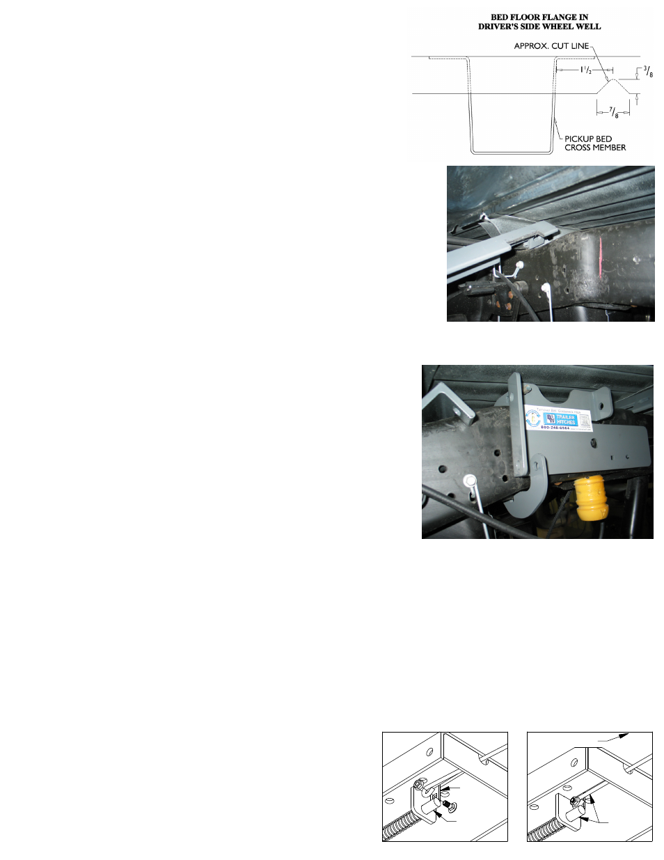
STEP 5 – BED FLANGE MODIFICATION
Some models of trucks will allow the crossmembers to slide between the frame
and bed without modification. If this is not possible a small notch needs to be
made in the flange on the driver’s side of the truck. (see diagram)
Locate the front truck bed cross member in the wheel well. Measure from the
back of the cross member and make a mark at 1 ½” this measurement is im-
portant. This will be the center point for the notch that is needed. Mark and cut
a 7/8”” wide by 3/8” tall notch.
STEP 6 – CROSS MEMBER INSTALLATION
The 1108 mounting kit is supplied with two angle crossmembers. The rear
crossmember has three notches and will be installed first. Slide the rear cross-
member between the frame and bed on the driver’s side. If necessary use the notch
cut into the bed flange in step 5. Make certain the leg of the angle with the oval holes
is facing toward the cab. After sliding the angle in about half way it may need to be
guided onto the other frame from the underside the truck. At this point the angle should
span between both frame rails and in front of the shock bracket on the passenger side.
Next using the notch over the shock bracket for clearance, roll the angle iron over the
bracket while sliding it toward the rear. It is important to hold the driver’s side of
the crossmember upward against the bed floor and forward against the bed
crossmember. Continue to slide it back until it is about four inches behind the four inch
hole that has been drilled in the bed. Next install the front angle in the same manor ex-
cept for the leg of the angle with the oval holes should face the rear of the truck during
installation. Slide it rearward just behind the shock bracket and leave until needed for
installation. When installed correctly the two angle legs with the holes should be facing
each other.
**** HAND TIGHTEN ALL HARDWARE IN STEPS 7 AND 8 ****
STEP 7 – INSTALL CLAMPING STRAP & SIDE PLATES
If the emergency brake cable has been removed from the frame, place a 5/16”
carriage bolt (included) through the small square hole in the driver side side-
plate, add a 5/16” nut loosely to hold in place. This will be used for attaching the
emergency brake cable bracket. Next you will need to install the clamping strap
and side plate on the driver side of the truck. Take a side plate clamp and posi-
tion around the frame approximately 6 ½” in front of the slotted hole on the side
of the frame. Next take the driver side sideplate and slide the bottom side of the
sideplate between the clamping strap and the frame (see picture). Guide the stud
on the clamping strap through the hole in the top of the sideplate place a ½” lock
washer and nut on the stud. Next place a ½” bolt through the hole in the bottom
of the clamping strap and the sideplate and add a ½” lock washer and nut. Next
install a pipe spacer between the side plate and the frame and place the ¾” bolt
through the sideplate, pipe spacer, and the frame then add a ¾” flat washer, lock
washer and nut. Repeat the process for the passenger side.
STEP 8 – INSTALL THE CENTER SECTION
Raise the center section into position between the cross members from beneath the truck, with the latch pin release handle on the
driver side. A lifting device, as described on page 1 will help. The round hitch receiver that protrudes from the top of the center sec-
tion must fit through the hole in the truck bed floor. Slide the angles against the center section (an adjustable wrench can be used to
stand the angles up if needed) and bolt together using six ½” x 1 ½” bolts. Place the bolts with a flat washer through the slots in the
cross member and through the holes in the center section and add a ½” lock washer and nut. Next bolt the side plates to the angle
cross members using a ½” x 1 ½” bolt through the side plate, through the angle and add a ½” flat washer, lock washer and nut.
STEP 9 – TIGHTEN HARDWARE
1. Tighten the center section to cross member bolts to 80 ft pounds. 2. Check to ensure the assembled center section is square
with the frame. 3. Tighten the ¾” side plate bolts to 120 ft pounds. 4. Tighten the bottom clamping strap bolts to side plate to 80 ft
pounds. 5. Tighten the clamping strap studs to 60 ft pounds. 6. Tighten the side plate to angle bolts 80 ft pounds. If the emergency
brake cable has been removed, take the 5/16” nut off the previously installed bolt. Place the emergency brake cable bracket over
the bolt, replace the nut and tighten.
LATCH
PIN
TAB
IN−LINE
DRIVER SIDE
STEP 10 – INSTALL LATCH PIN RELEASE HANDLE
WARNING: LATCH PIN WILL NOT FUNCTION PROPERLY IF HANDLE IS NOT
INSTALLED CORRECTLY.
Install the latch pin release handle by inserting it through the slot in the end
of the center section on the driver’s side of the truck. Align the handle eyelet
with the square hole in the latch pin so the handle is in line with the latch
pin as shown. Secure the handle to the pin with the 5/16 X 3/4” carriage
bolt and 5/16” locking flange nut as shown. Note: The included 5/16” cap
screw can replace the carriage bolt if wrench access on the “cab side” of the
handle is limited. Tighten the nut until it is secure. Do not over-tighten and
deform the handle eyelet.