Before installing, Installation instructions, Ball location – B&W Trailer Hitches 1108R User Manual
Page 2: Remove spare tire before installing hitch, Safety notice, Long and short bed installation = 47
An overhead-lifting device, such as chain falls, engine hoist, or cable come-a-long, can be used to
lift the center section of the hitch in place. Lower a loop of rope or chain through the 4” hole in the
truck bed floor and attach it to the latch pin in the round hitch receiver tube in the center section.
Use the lifting device to raise the center section until the round hitch receiver tube that protrudes
from the center section fits in the 4” hole in the truck bed floor. Maintaining upward pressure may
facilitate fastening the crossmember to the center section, especially if the truck bed floor has been
distorted downward from heavy use. If you use an overhead-lifting device, it should be disconnected
before squaring the center section across the frame, installing the sideplates and torquing fasteners.
INSTALLATION INSTRUCTIONS
BALL LOCATION:
STEP 1 – MARKING AND CUTTING 4 INCH HOLE IN TRUCK BED
Begin by measuring for the correct hole location in the truck bed floor. Measure from the tail gate end of the truck bed floor by hook-
ing a tape measure over the end of the truck box and mark the floor at 47”. Next find the center point between the wheel wells,
where these marks intersect with the first measurement will be the center point of your four inch hole. This Location is critical to
the correct installation of the B & W Turnoverball™ so measure, mark and saw carefully. Make a four inch hole at this location. B&W
recommends using a four inch hole saw, however the hole can be cut by other means. If your truck has a spray-in bed liner you will
need to take into account when you are measuring to add the thickness of the applied liner that has been sprayed over the end of the
bed. If your truck has a Drop-in plastic bed liner, you may saw through both, but it is more difficult to accurately locate the midpoint
between the fender wheel wells, and to be sure that the bed liner does not move when sawing the hole. Once you have the four inch
hole in the bed use a deburring tool or a die grinder and carefully remove the burr from the under side of the bed around the hole.
STEP 2 – HEAT SHIELD REMOVAL
Remove the heat shield located above the rear axle under the truck bed.
STEP 3 – BRAKE CABLE & FUEL LINE BRACKET
On 2004 and older trucks the emergency brake cable located on the outside of the
driver’s side frame will have to be relocated. Knock the mounting stud out of the frame
and discard. A relocating bolt is furnished in the kit and will be installed later.
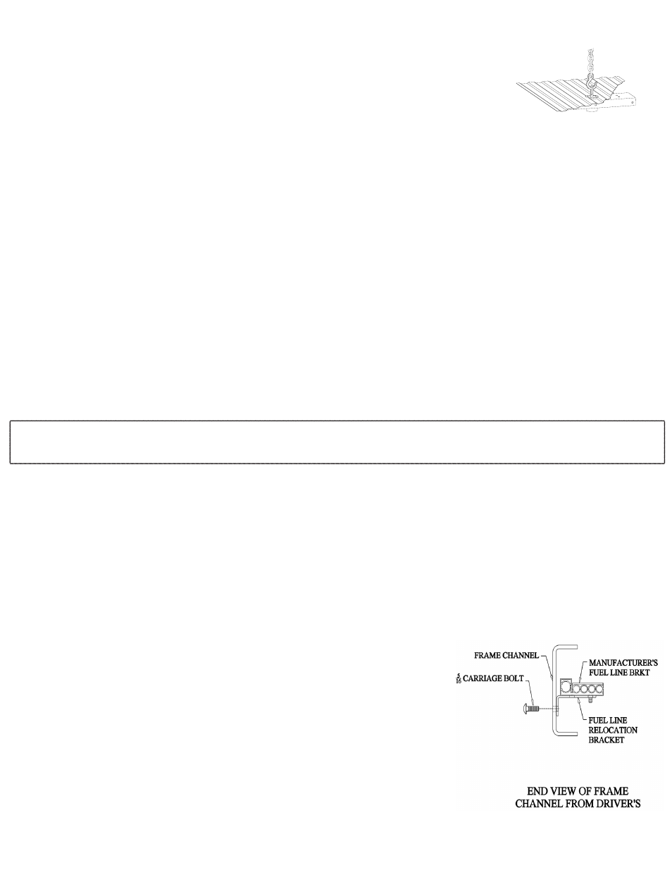
On trucks equipped with a gasoline engine it may be necessary to relocate a fuel line
bracket. If the oval hole in the driver’s side frame just above the axle is partially blocked
you will need to relocate the bracket. This bracket may be held by a nut and stud on the
outside of the frame or by a plastic retainer pushed through the frame from the inside.
Remove the nut or push the plastic retainer through the frame so the bracket can be
rotated 90 degrees. Next install the relocation bracket supplied in the kit. Using a 5/16”
carriage bolt and flange nut bolt the bracket to the inside of the frame as shown in the
diagram. The factory fuel line bracket can now be reinstalled on the relocation bracket.
If there is a threaded stud on the bracket, Place the stud through the outer hole and
fasten with the nut removed earlier. If the bracket has a plastic retainer, push it through
the inner hole in the relocation bracket.
WARNING
Most trucks have FUEL LINES and/or BRAKE LINES and/or ELECTRICAL WIRES located along the frame rails where B&W Turnoverball™
hitches install. Carefully examine the location of fuel lines, brake lines and electrical wires BEFORE INSTALLATION. Be certain you
will not damage fuel lines, brake lines or electrical wires when positioning hitch components, drilling holes, tightening fasteners, and
lifting and lowering the truck bed. The fuel tank vent, located on top of the gas tank, can be easily damaged during the installation
of the hitch components. Care must be taken when positioning the front crossmember and center section components.
WARNING
On Short bed trucks, BEFORE INSTALLING THIS HITCH, check for adequate turning clearance between the front of all of your trailers
and the truck cab.
WARNING
DO NOT invert the ball in the socket when carrying heavy loads on 2 wheel drive trucks. The ball may hit the top of the differential.
Remove the ball from the socket before loading. A plug for the socket is available from B & W.
BEFORE INSTALLING-
OVERHEAD LIFTING DEVICE
STEP 4 – EXHAUST BRACKET REMOVAL
On 2005 and newer trucks equipped with a diesel engine the tail pipe will need to be lowered. First remove the tail pipe bracket just
behind the rear tire on the passenger side. This will be reattached later.
****SAFETY NOTICE*****
On 2008 and newer trucks we recommend removing
the spare tire heat shield to avoid injury.
REMOVE SPARE TIRE BEFORE INSTALLING HITCH.
Long and short bed installation = 47”