B&W Trailer Hitches 1104R User Manual
Page 4
Copyright 2014
B&W Custom Truck Beds, Inc.
ALL RIGHTS RESERVED
1104R 05 01 2014
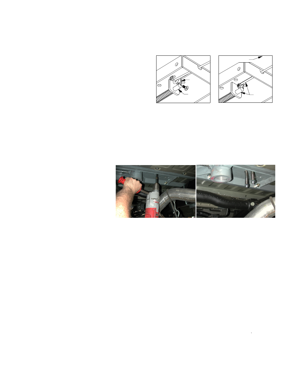
STEP SEVEN - INSTALL SAFETY CHAIN BRACKETS
To install the safety chain brackets it is necessary to drill four 1/2” holes through the truck bed floor. Drill
the holes from beneath the truck, through the two holes located on each side and furthest away from the
round receiver tube in the center section. This will locate the safety chain brackets in the lowest point of
the floor corrugation. Drop a U-bolt through each pair of holes from the topside of the truck bed floor. Place
a spring and lock nut on each of the four legs. Tighten the lock nuts until 1/4” of thread extends through the
lock nut.
STEP EIGHT - ENGAGE LATCH PIN
Retract the latch pin by pulling the handle all the way out until it stops and then rotating it clockwise. Place
the 2-5/16” ball in the hitch receiver. Engage the latch pin by rotating the handle counter clockwise. Be cer-
tain the latch pin passes through the holes in the 2-5/16” ball and fully engages through the hitch receiver.
Finally, remove and lightly grease the four corners on the square base of the 2-5/16” ball.
LATCH
PIN
TAB
IN−LINE
DRIVER SIDE
STEP SIX – INSTALL LATCH PIN RELEASE HANDLE
WARNING: LATCH PIN WILL NOT FUNCTION PROPERLY IF HANDLE IS NOT INSTALLED CORRECTLY.
Install the latch pin release handle by inserting it through the slot in the end of the center section on the
driver’s side of the truck. Align the handle eyelet with the square hole in the latch pin so the handle is in
line with the latch pin as shown. Secure the handle to the pin with the 5/16 X 3/4” carriage bolt and 5/16”
locking flange nut as shown. Note: The included 5/16” cap screw can replace the carriage bolt if wrench
access on the “cab side” of the handle is limited. Tighten the nut until it is secure. Do not over-tighten
and deform the handle eyelet.