B&W Trailer Hitches 1104R User Manual
Page 3
STEP THREE - CROSS MEMBER INSTALLATION
Select the rear crossmember that is notched on one side. With the long (2 1/2”) side of the angle iron
pointing down and the short (2”) side with the notches facing the rear of the truck, position it across the
top of the frame rails, between the bed and frame, by pushing it through the opening in the wheel well on
the driver’s side of the truck. Make certain that the notches fit tightly against the truck bed crossmember
on the back of the truck. Select the second crossmember without notches and place it between the bed
and frame, by pushing it through the opening in the wheel well on the driver’s side of the truck. With the
two crossmembers approximately parallel, position them about 9” apart, spaced in front and behind the
hole in the truck bed floor and hanging over the same distance on each side of the frame rails.
STEP FOUR
With the latch pin mechanism on the driver’s side
of the truck, raise the center section of the hitch
into position between the crossmembers from
beneath the truck. The round tube hitch receiver
that protrudes from the center section must fit through the hole in the truck bed floor. Fasten the center
section to the crossmembers using seven of the 1/2” x 1 1/2” bolts. Start these bolts through the holes
in the crossmember and place a flat washer, a lock washer and nut on each bolt DO NOT fully tighten
at this time.
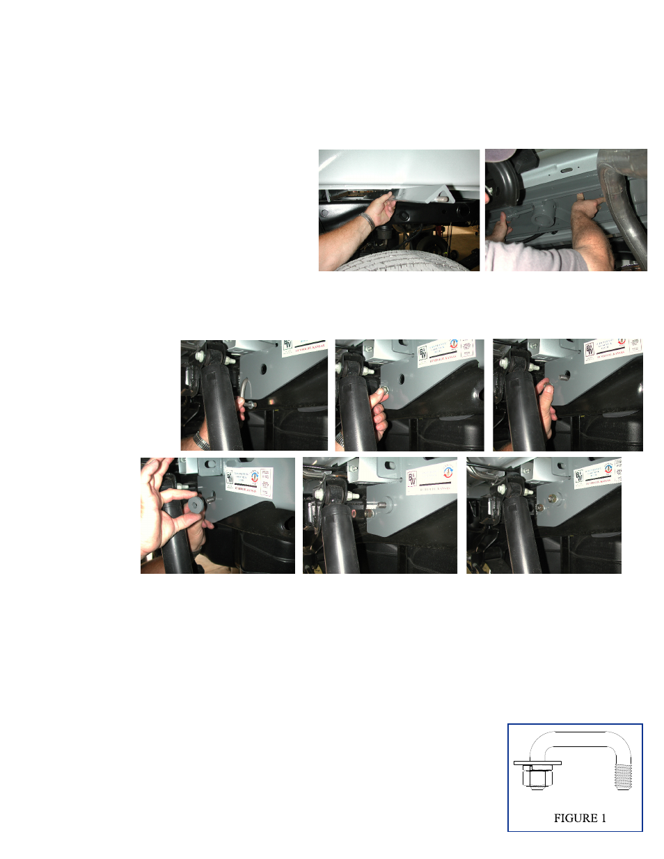
STEP FIVE- INSTALL SIDEPLATES
Vehicle equipment with a NO-CAP fuel neck have a drain/vent hose attached to the frame on the driver side
in the area where the rear shock mounts to the frame. This hose must be detached from the frame and
relocate before installing the sideplate for the drivers side.
Install the sideplates by placing the top back hole over the stud on the rear cross member with a flat washer,
lock washer, and nut, then bolt the front flange of the sideplate to the front cross member with a bolt, flat
washer , lock washer, and nut DO NOT fully tighten at this time. The two holes at the front of the side-
plates should align with two holes in the frame behind the shock and shock mount. Next place a flat washer,
lock washer, and nut on one end of the 2” u-bolt. (see fig. 1) Place the other end into the smaller hole at the
front of the sideplate and twist through the frame until the threaded end is protruding out the other hole of
the sideplate (as shown in pictures above). Next place the sideplate insert over this
end, being sure that the straight edge of the insert lines up with the straight edge
of the hole of the sideplate and is pushed into the frame all the way. (The insert will
not set flush against the sideplate when tightened if it is not properly aligned.) Then
place a lock washer and nut on the u-bolt and tighten both ends of the u-bolt to 45
ft. lbs. Repeat for other side. Next tighten the seven center section bolts to 90 ft.
lbs. Then tighten the two bolts that fasten the sideplates to the cross members on
each side to 90 ft. lbs.