B&W Trailer Hitches 1316R User Manual
Page 3
STEP 3
With the latch pin on the driver’s side and the socket offset
to the front of the truck, raise the center section over the
differential and in between the cross members. Push the
center section up to the floor while guiding the ring into the
four inch hole in the truck bed. Thread four of the 1-1/2”
bolts with a lock and flat washer into the front bar from
inside the center section leaving them loose at this time.
Next with the rear angle against the rear of the center sec-
tion install three 1-1/2” bolts through the center section
and angle securing with a lock and flat washer on each. DO
NOT fully tighten at this time.
STEP 4
The sideplates will have to be installed with the center sec-
tion bolts still loose, so that the sideplates can be positioned
between the bar and angle. With the long flange to the front
, place the side plate between the cross members and thread
a 1-1/2” bolt with a flat and lock washer into the bar. Install
the bolt with two flat washers and a lock washer and nut
through the sideplate ear and angle. Repeat this procedure
on the passenger side.
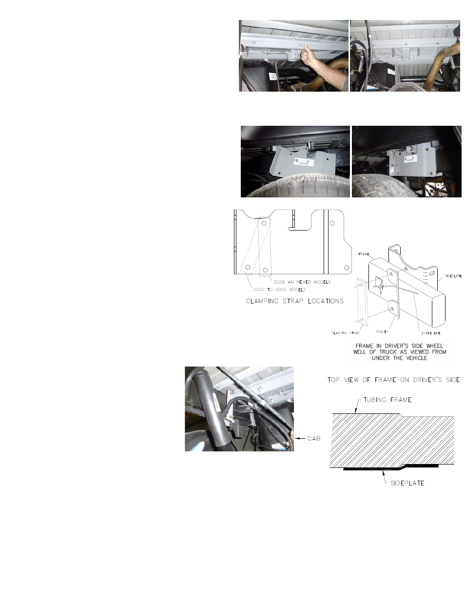
STEP 5
Attach the sideplates to the frame. On 2002 though 2005
model trucks the top front and lower front holes will be
used. On 2006 model trucks the top front and middle lower
holes will be used (see diagram). Install the 1/2” x 4-1/2”
bolts though the holes in sideplates above and below the
frame using the correct holes per year of truck as stated
above. Install the clamping straps on the inside of the frame
over the bolts. On 2006 model trucks a brake line spacer
will need to be added on the drivers side front before the
clamping strap is installed (see diagram). This will allow the
needed clearance between the frame and clamping strap
for the brake line. On the 2002 though 2005 model trucks
the clamping strap will install between the brake line and
frame. Secure the clamping straps with lock washers and
nuts. Hand tighten until snug.
STEP 6
The sideplates have a double bend offset
near the rear clamping bolts that will engage
the offset in the truck frame, and create a
wedging lock to prevent the hitch from slid-
ing forward on the frame. Before the final
bolt tightening, position the sideplate so
that the offset in the sideplate is mated
against the offset in the frame, but not
riding up on it so that there would be a
gap between the clamping flange and the
frame. Install the wedging “J” bolts in the frame hole in front of
the sideplate and through the hole in the sideplate front flange,
and install the lock washer and nut. At this time, tighten this nut
only enough to achieve the correct contact between the frame and
sideplate offsets. Loosely install all of the remaining hardware in the
center section.
STEP 7
Tighten the hitch hardware in the following sequence. Tighten the rear sideplate clamping bolts and then the front
sideplate clamping bolts to 60 ft-lbs. of torque. Tighten them slowly, alternating from the top bolt to the bottom so that
they tighten evenly. Also make certain that the bolts are perpendicular (90 degrees) to the truck frame so that the bolts
will not loosen later. Center the front bar crossmember across the frame and tighten bolts to the sideplate. Tighten
the center section bolts to the front bar to 90 ft.-lbs. of torque. Center the angle iron across the frame, and tighten the
bolts to the sideplates and to the center section, also to 90 ft.- lbs. Tighten the “J” bolts to 40 ft. lbs. of torque.