B&W Trailer Hitches 1067R User Manual
Page 4
Copyright 2014
B&W Custom Truck Beds, Inc.
ALL RIGHTS RESERVED
1067R 05 01 2014
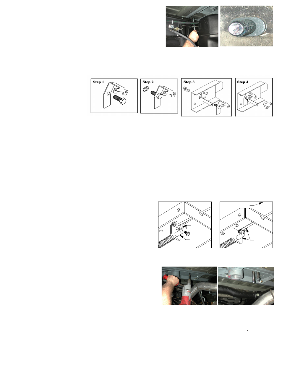
STEP ELEVEN - INSTALL SAFETY CHAIN U-BOLTS
To install the safety chain brackets (8) it is necessary to drill four 1/2” holes through the truck bed floor. Drill the holes
from beneath the truck, through the two holes located on each side
and closest to the round receiver tube in the center section.
This will locate the safety chain brackets (8) in the lowest point of
the floor corrugation. Drop a U-bolt through each pair of holes from
the topside of the truck bed floor. Place a spring and lock nut on each
of the four legs. Tighten the lock nuts until 1/4” of thread extends
through the lock nut.
STEP THIRTEEN - ENGAGE LATCH PIN
Retract the latch pin by pulling the handle all the way out until it stops and then rotating it clockwise. Place the 2-5/16”
Ball (10) in the hitch receiver. Engage the latch pin by rotating the handle counter clockwise. Be certain the latch pin
passes through the holes in the 2-5/16” Ball and fully engages through the hitch receiver. Finally, remove and lightly
grease the four corners on the square base of the 2-5/16” Ball.
STEP TWELVE -REPLACE EXHAUST BRACKET
Reinstall the exhaust hanger brackets and the spare tire if removed during step 2
.
When completed, tighten all the hardware in this order: Tighten the center section bolts to the cross members to
80 ft. lbs. and then make certain the hitch is square with the frame. Tighten the ¾” sideplate bolts to 120 ft lbs.
and then tighten the frame clamping U-bolts. Tighten the U-bolts slowly; alternating between the top and bottom
legs of the u-bolt until equally tightened to a maximum of 40 ft lbs. This torque may not be obtained without bend-
ing the sideplate some. This is normal and will not hinder the function of the hitch. Next tighten the three carriage
bolts on each sideplate to 60 ft. lbs and then tighten the sideplates to the front crossmembers to 80 ft. lbs.
STEP NINE - TIGHTEN HARDWARE
STEP EIGHT
Install the ½-inch x 8 ¼-inch U-bolt from inside the frame through the
holes in the sideplate above and below the frame, use a lock washer
and nut on each end of the U-bolt. Repeat this procedure on the pas-
senger side of the truck with the other sideplate. (While installing
the U-bolts around the frame use caution not to damage or pinch the
wiring harness or brake lines).
WITH FACTORY INSTALLED BRAKE CONTROL
(if no factory install brake control is present continue to Step 8B)
Step 8A: To relocate the brake relay; first insert a 3/4” X 2-1/2” bolt through the relay
bracket. (see Step 1) Next slide a frame bushing onto the bolt. (see Step 2) The hole in the frame is oval shaped. B&W
provides a frame bushing that converts the oval hole into a round hole. From the inside of the frame insert the bolt
with bracket and bushing into the frame and sideplate making certain that the frame bushing is in the oval hole in the
frame. Fasten the bracket with a 3/4” lock washer and nut on the outside of the side plate. (see Step 3) Next install
the brake control relay by sliding
its two bolts onto the relay bracket
and tighten. (see Step 4) Repeat the
bolting process on the passenger side
minus the relay bracket. Continue to
Step Nine.
WITHOUT FACTORY INSTALLED BRAKE CONTROL
(if the truck is equipped with a factory installed brake control see Step 8A)
Step 8B:
Install the ¾-inch by 2 ½-inch bolt. Place a flat washer and frame insert on the 3/4” bolt and install the
bolt from inside the frame through the lower rear hole in the side plate. Fasten with a lock washer and nut. (The hole
in the frame is a slotted hole, and B&W provides an insert that converts the slotted hole to a 3/4” round hole).
LATCH
PIN
TAB
IN−LINE
DRIVER SIDE
STEP 10 – INSTALL LATCH PIN RELEASE HANDLE
WARNING: LATCH PIN WILL NOT FUNCTION PROPERLY IF HANDLE IS NOT INSTALLED CORRECTLY.
Install the latch pin release handle by inserting it through the slot in the
end of the center section on the driver’s side of the truck. Align the handle
eyelet with the square hole in the latch pin so the handle is in line with
the latch pin as shown. Secure the handle to the pin with the 5/16 X 3/4”
carriage bolt and 5/16” locking flange nut as shown. Note: The included
5/16” cap screw can replace the carriage bolt if wrench access on the
“cab side” of the handle is limited. Tighten the nut until it is secure. Do
not over-tighten and deform the handle eyelet.