Installation instructions, Warning, Notice – B&W Trailer Hitches 1067R User Manual
Page 2
INSTALLATION INSTRUCTIONS
STEP ONE - REMOVE SPARE TIRE AND HEAT SHIELD
The heat shield under the bed floor must either be removed or a section cut out for the
hitch assembly to be installed.
A) Remove the heat shield from in front of the back crossmember.
B) Remove the heat shield from the back of the crossmember located near the front
of the wheel well.
STEP TWO - REMOVE EXHAUST BRACKET
To ease installation of the center section, remove the lower exhaust bracket. Simply pull
the hanger rod out of the rubber bracket hole and a 6” to 8” wood block can then be
positioned between the exhaust pipe and frame of the truck. This will increase your clearance between the top of the
exhaust pipe and the bottom of the truck bed floor. (Caution: Exhaust pipe may be hot).
STEP THREE- MARKING AND CUTTING 4 INCH HOLE IN TRUCK BED FLOOR
Begin by verifying and measuring the correct hole location in the truck bed floor. Measure from the back end (tail- gate
end) of the truck bed floor by hooking a tape measure over the back of the truck box and mark the floor at the correct
measurement. Next, center the location between the wheel wells. This will be the center point for the four inch hole. This
location is critical to the correct installation of this hitch, so measure, mark and saw carefully. If the truck has a plastic
bed liner, you may drill through both, but it is more difficult to accurately locate the midpoint between the fender wheel
wells, and to be sure that the bed liner does not move while sawing the hole. Make a 4 inch hole at this location using a
four inch hole saw, or by marking a 4 inch circle and cutting it out with a saber saw equipped with a metal cutting blade.
STEP FIVE - CROSS MEMBER INSTALLATION
Place the 48” front cross member (1) between the truck frame and bed floor using
the notch made in step four. Be sure the holes in the cross member are facing
to the rear of the truck. Slide the cross member across both frame rails. Using
the rubber O-ring provided, secure a 1/2” 1-1/2” long bolt into the second hole
in the cross member from the drivers side. Slide the
crossmember forward to the front edge of the 4” hole
in the bed. Next install the 46 1/2
”
rear cross member
bar (2) between the truck frame and bed floor. Rotate
the rear cross member a quarter turn so the threaded
holes are offset to the bottom of the bar and slide back
until there is enough room for the center section to be
placed between the two cross members.
Long Bed 49
1
/
2
inches
Short Bed 44
1
/
4
inches
Truck
Ball
Type
Location
TIP: B&W uses a 3/4”
piece of plywood as a
drilling guide to pre-
vent the hole saw from
moving while drilling
the 4” hole in the truck
bed.
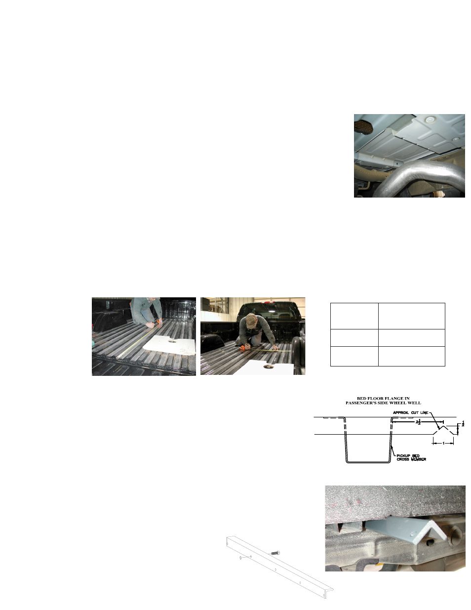
STEP FOUR - BED FLANGE MODIFICATION
Install the two cross members. They will be installed by sliding them from inside
the wheel well, above the tire, through the gap between the bed and the truck’s
frame and across until they span the frame rails. The gap between the bed and
frame is large enough to allow this, but the gap is partially obstructed by a sheet
metal flange (about 1” in height) that is hanging down from the bottom of the
truck bed floor. (See diagram and photos). A small notch needs to be made
in this flange on the passenger side of the truck. Locate the center truck bed
cross member. Measure over 2 1/2” from the front of the cross member and
make a mark. This will be the center point of the notch that is needed. Mark
a 1” wide by 1/2” tall notch. Remove the metal of the marked area with sheet
metal sheers. This will allow the front angle iron crossmember to be installed.
WARNING
On Short bed trucks, BEFORE INSTALLING THIS HITCH, check for adequate turning clearance between the front of all
of your trailers and the truck cab.
WARNING
DO NOT invert the ball in the socket when carrying heavy loads on 2 wheel drive trucks. The ball may hit the top of
the differential. Remove the ball from the socket before loading. A plug for the socket is available from B & W.
NOTICE
In some Truck models, plastic wheel well liners are present which extend past the side plate installation location on the
frame. A portion of the liner may need to be cut away over the area where the side plate will be installed.