B&W Trailer Hitches 1062R User Manual
Page 4
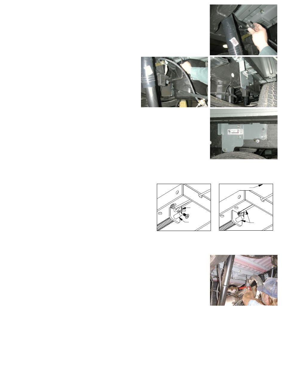
Next attach the rear bar to the side plate flange threading a ½” by 1 ½” bolt into the
bar and tighten both the front and rear flanges at this time to 80 ft pounds.
Install the ½-inch x 8 ¼-inch U-bolt from inside the frame through the holes in the
sideplate above and below the frame, use a lock washer and nut on each end of the U-
bolt. Repeat this procedure on the passenger side of the truck with the other sideplate.
Install the ¾-inch by 2 ½-inch bolt through the lower rear hole in the sideplate. The
hole in the frame is a slotted hole, and B&W provides an insert for the slotted frame
hole to convert it to a ¾” round hole. This insert is installed to the inside of the truck
frame, and it can be positioned in three different positions; the center position is on
one side of the insert, and the offset position is on the
other side, and can be offset either forward or rear ward.
Look at the position of the sideplate hole relative to the
frame slot to select the appropriate position for the frame
insert. Install the insert over the ¾-inch bolt and into the
frame, and install the flat washer, lock washer, and nut.
When completed, make certain the hitch is square with
the frame. Tighten remaining hardware in this order:
Tighten the ¾” side plate bolts to 120 ft pounds. Tighten
the frame clamping U-bolts slowly, alternating between
the top and bottom legs of the U-bolt until equally tight-
ened to 60 ft pounds. 5. Tighten the two carriage bolts
to 60 ft pounds.
STEP EIGHT - INSTALL SAFETY CHAIN BRACKETS
To install the safety chain brackets it is necessary to drill four 1/2” holes through the
truck bed floor. Drill the holes from beneath the truck, through the two holes located
on each side of the round receiver tube in the center section. This will locate the safety
chain brackets in the lowest point of the floor corrugation. Drop a U-bolt through each
pair of holes from the topside of the truck bed floor. Place a spring and lock nut on
each of the four legs. Tighten the lock nuts until flush with the bottom of the U-bolts.
STEP NINE - ENGAGE LATCH PIN
Retract the latch pin by pulling the handle all the way out until it stops and then ro-
tating it clockwise. Place the 2-5/16” ball in the hitch receiver. Engage the latch pin
by rotating the handle counter clockwise. Be certain the latch pin passes through the
holes in the 2-5/16” ball and fully engages through the hitch receiver. Finally, remove
and lightly grease the four corners on the square base of the 2-5/16” ball.
Copyright 2014
B&W Custom Truck Beds, Inc.
ALL RIGHTS RESERVED
1062R - 05 01 2014
LATCH
PIN
TAB
IN−LINE
DRIVER SIDE
STEP SEVEN – INSTALL LATCH PIN RELEASE HANDLE
WARNING: LATCH PIN WILL NOT FUNCTION PROPERLY IF HANDLE IS NOT INSTALLED CORRECTLY.
Install the latch pin release handle by inserting it through the
slot in the end of the center section on the driver’s side of the
truck. Align the handle eyelet with the square hole in the latch
pin so the handle is in line with the latch pin as shown. Secure
the handle to the pin with the 5/16 X 3/4” carriage bolt and
5/16” locking flange nut as shown. Note: The included 5/16” cap
screw can replace the carriage bolt if wrench access on the “cab
side” of the handle is limited. Tighten the nut until it is secure.
Do not over-tighten and deform the handle eyelet.