Application update – B&W Trailer Hitches 1062R User Manual
Page 3
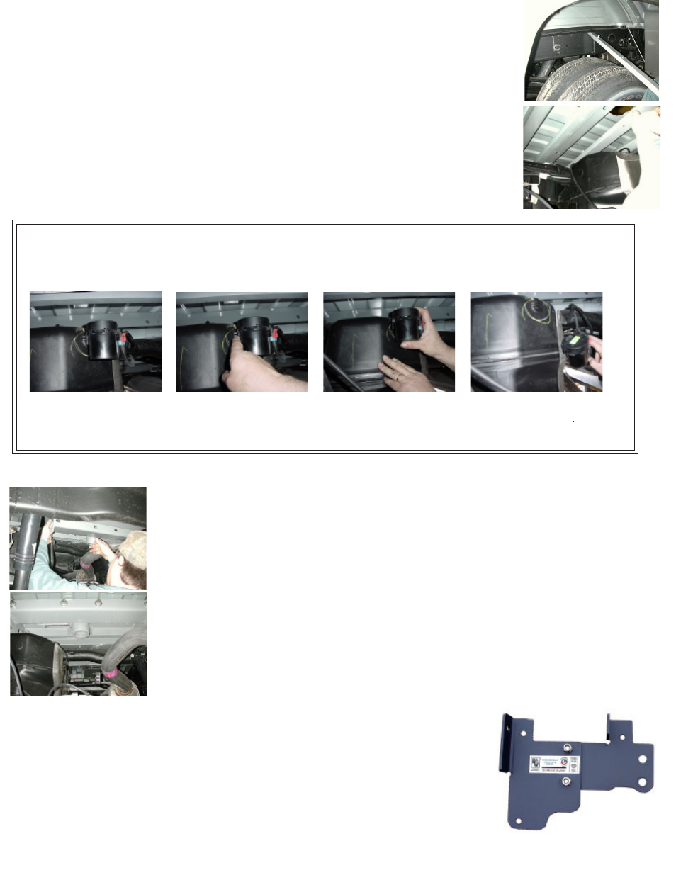
STEP FIVE - INSTALL THE CENTER SECTION
Raise the center section into position with the socket top pointed upward, and the latch
pin to the driver’s side. Raise the center section over the differential, and angle it up over
the exhaust pipe until it clears the fuel tank, and then move it back over the fuel tank as
shown. There are fuel lines and wiring coming out of the top of the fuel tank, so you must
avoid damaging those by holding the center section tightly against the bottom of the truck
bed floor while moving it. Insert the socket top into the 4-inch hole in the floor. If you are
using an overhead lifting device, attach it to the latch pin, and apply a small amount of up-
ward pressure to the truck bed floor, to make bolting easier. Move the front bar against the
center section sliding the pressed bolt into the matching hole in the center section. Install
two of the 2 1/4” x 1/2” bolts through the bar and into the center section while placing a
flat washer, lock washer, and nut on the bolt threads. Next thread four 1 1/2” bolts with flat
and lock washers through the center section and into the rear bar. Shift the bar sideways
until it is centered across the frame. Also twist the assembly so that it is parallel with the
bed crossmembers and tighten all center section fasteners at this time.
STEP SIX - INSTALL SIDEPLATES
Next install the sideplates. The driver’s sideplate is shown, with the bent flange to the
front, and the large holes to the rear. Attach the two pieces of the sideplate together
with ½” carriage bolts. The carriage bolts should be inserted into the square holes from
the backside of the sideplates and fastened using a lock washer and nut on each bolt.
This can be completed before installing on the frame rail.
Attach the flange on the sideplate to the front bar by placing a 1/2” x 2 1/4” bolt through
the bar and sideplate; secure with a flat washer, lock washer and nut.
Step 1:
Locate the fuel valve.
Step 2:
Disengage the lock-
ing pin.
Step 3:
Slide fuel valve from
bracket.
Step 4:
Install Turnoverball™
Center Section.
APPLICATION UPDATE:
The new fuel valve mounted on the rear of the fuel tank on 2004 and newer model trucks equipped with gas
engines, will make it more difficult to install the Turnoverball
TM
center section. This fuel valve can be easily
removed and replaced to ease installation. Please follow the following instructions:
Step 5: Replace fuel valve to bracket on fuel tank
.
STEP FOUR - INSTALL CROSSMEMBERS
The next step is to install the two crossmembers. They install through the gap between the
bed and the frame. The front crossmember can be identified by the bolt pressed into one
hole. Install the front bar by sliding it across the frame rails between the two bed cross
members where the four inch hole has been cut. Slide the bar in and center between the
frame rails. Next rotate the bar so that the pressed bolt is above the fuel tank and the threads
are facing toward the rear of the truck. Now it can be pushed forward on the frame toward
the front bed crossmember, on the higher part of the frame. It is difficult to rotate the bar
on the higher frame, so be sure to rotate it before moving it forward. The rear crossmem-
ber installs between the double bed crossmembers. Push the bar in lying horizontal until
centered and then rotate it to vertical, making sure that the threaded holes are positioned
at the bottom of the bar. Position this bar right behind the bed crossmember that is closest
to the 4” hole in the truck bed. The holes in this bar are threaded to receive ½ inch bolts.