Oon n- -t th he e- -v ve eh hiic clle e – AMMCO 800 On-The-Vehicle Brake Lathe User Manual
Page 25
AMMCO 800 On-The-Vehicle Brake Lathe • 19
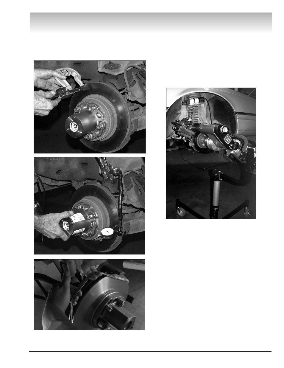
13.5 Inspect the rotor after machining to verify that
the rotor runout and thickness meet manufacturer’s
specifications.
13.6 Remove the chatter band and hub adapter.
Setup for Opposite Side Vehicle Rotor
Resurfacing
14.0 To cut the brake rotor on the opposite side of
most vehicles, the 800 brake lathe most be rotated to
its inverted position. To invert the lathe loosen the
pivot-locking lever on the portable stand system.
Adjust to an angular position, as done for the first
rotor, to assure lathe clearance during the refinishing
process, then tighten the pivot-locking lever.
14.1 Rotate the spindle manually, using the motor
handwheel, to position the adjustment knobs (red and
blue) to the up position, and insert the lock pin (yellow)
into the runout adjustment head.
14.2 After the 800 brake lathe has been attached
to the vehicle, it is not necessary to center the cutting
head assembly as that was accomplished on the first
rotor.
O
On
n-
-T
Th
he
e-
-V
Ve
eh
hiic
clle
e