Oon n- -t th he e- -v ve eh hiic clle e – AMMCO 800 On-The-Vehicle Brake Lathe User Manual
Page 20
14 • AMMCO 800 On-The-Vehicle Brake Lathe
O
On
n-
-T
Th
he
e-
-V
Ve
eh
hiic
clle
e
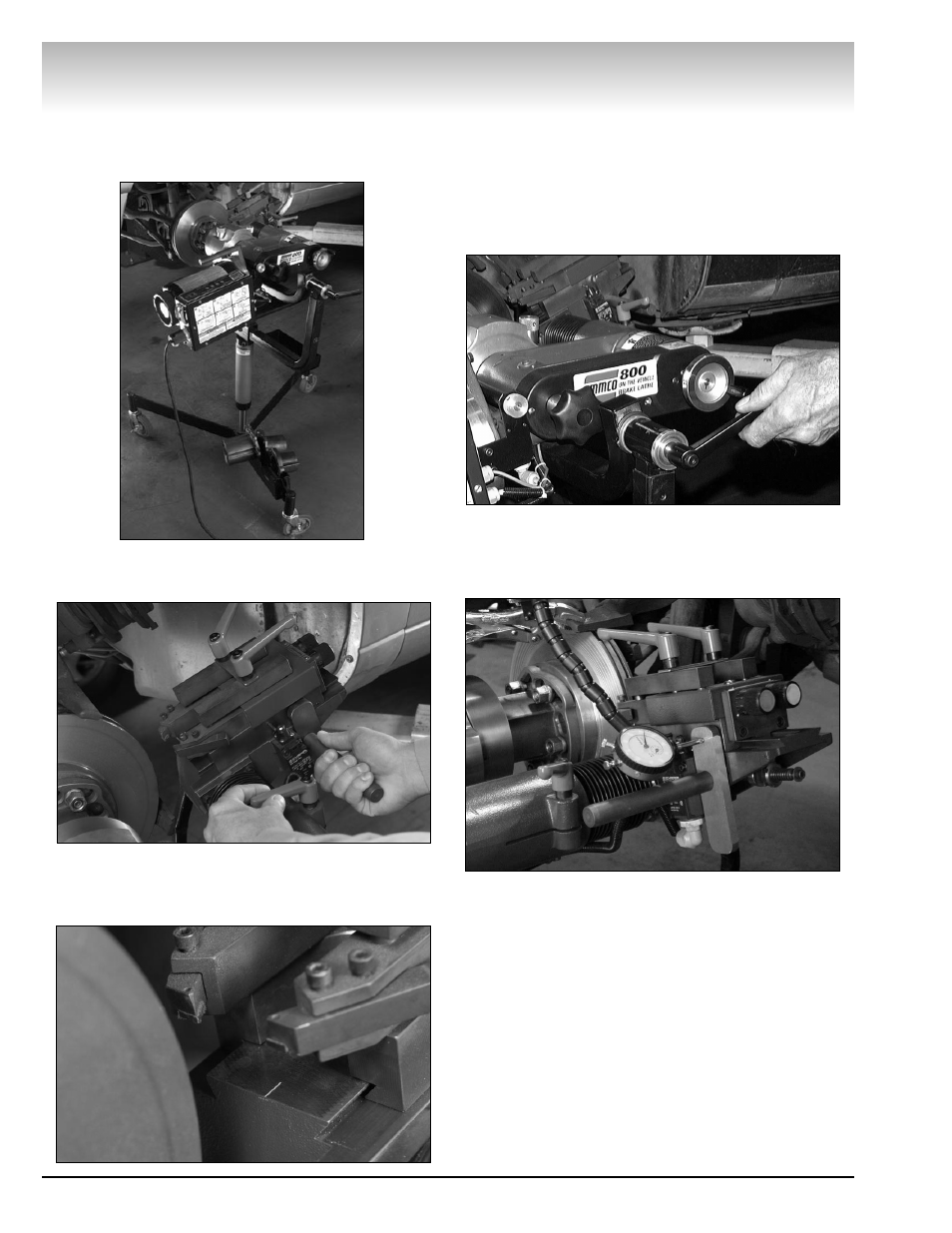
Cutting Head Assembly Positioning
9.0 For each different vehicle, the cutting head
assembly may need re-centering.
9.1 Loosen the head centering lock lever.
9.2 Position the cutting head assembly at a location
so the centerline mark on the head is centered on the
width of the brake rotor. Once positioned, retighten
the head centering lock lever.
9.3 Loosen the pivot-locking lever on the portable
stand system and rotate the 800 brake lathe to an
angular position that allows the cutting head assembly
to travel the full length of the rotor face without any
interference. This will assure lathe clearance during
the refinishing process. After this adjustment has
been completed, tighten the pivot-locking lever.
9.4 Attach the dial indicator and clamp system to
the vehicle wheel suspension and position the end of
the stylus on the target surface perpendicular to the
cutting head assembly.
The Lathe is Shown in Position