Oon n- -t th he e- -v ve eh hiic clle e, Caution – AMMCO 800 On-The-Vehicle Brake Lathe User Manual
Page 23
AMMCO 800 On-The-Vehicle Brake Lathe • 17
The mirror maybe used to view the rear surface.
11.31 After the scratch cut is performed reattach
the dial indicator to the target.
11.32 Read the runout. If runout is 0.004-inch or
less make no adjustments and proceed with the cut.
If the runout is more than 0.004-inch turn the power
switch off and re-engage the head lock pin (yellow).
11.33 Turn the power back on.
11.34 Use very small movements of the adjust-
ment knobs (red and blue) to decrease the indicator
movement to read less than 0.004-inch.
11.35 Switch power OFF. Disengage the head lock
pin (yellow) and move the indicator away from the tar-
get.
11.36 Proceed with cutting the rotor.
Note: It is not necessary to make another scratch
cut because the cutter head has not moved signifi-
cantly since the lock pin (yellow) was re-enaged.
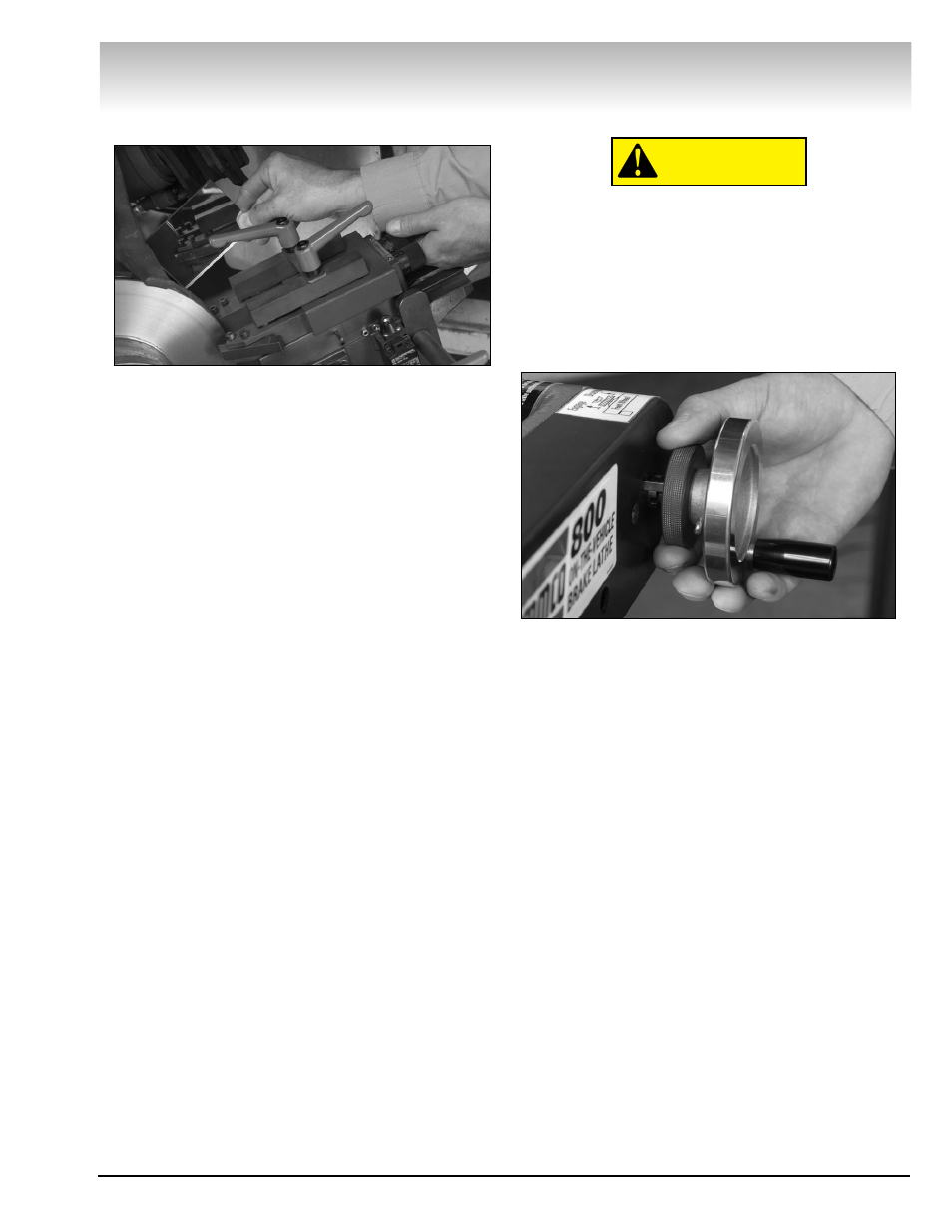
11.4 Switch power ON. With both cutting tips
backed away from the rotor, advance the carbide
inserts toward the center of the rotor diameter, using
the feed handwheel, being careful not to run the car-
bide inserts into the hub portion of the rotor.
11.5 Reposition carbide inserts to the cleanup
position by turning each insert adjustment knob clock-
wise one revolution, plus 0.004-inch cut depth for
resurfacing each side of the rotor. Make sure the tool
holder locking levers are locked in place before engag-
ing feed.
Completing the Cut
For optimum results, once the automatic
feed is engaged, do not disturb the lathe or
stand during the cut or damage to the rotor
may result.
12.0 Engage feed by pushing the feed engage-
ment knob (gray) forward into the slots. It is located
just behind the feed handwheel. The 800 brake lathe
will now feed the carbide inserts outboard at the rate
of .004-inch per revolution of the lathe spindle.
CAUTION
O
On
n-
-T
Th
he
e-
-V
Ve
eh
hiic
clle
e