Brake lathes – AMMCO 6000 Heavy Duty Drum/Disk Lathe User Manual
Page 8
Electrical Wiring Requirements
The lathe is factory wired to a disconnect box which should be
grounded to the power supply box in accordance with local code
requirements to protect the operator from shock.
The lathe is grounded to the disconnect box through the flexi-
ble conduit. The flexible conduit should not be removed or
eliminated.
This box is to be mounted to the wall behind the machine.
A qualified electrician should complete the hook-up to line
power of 220 VAC, 50~60 Hz, Single Phase, 20 amps.
Before operating the lathe be sure the drive motors are con-
nected at the terminal plate as shown in Fig. 1.
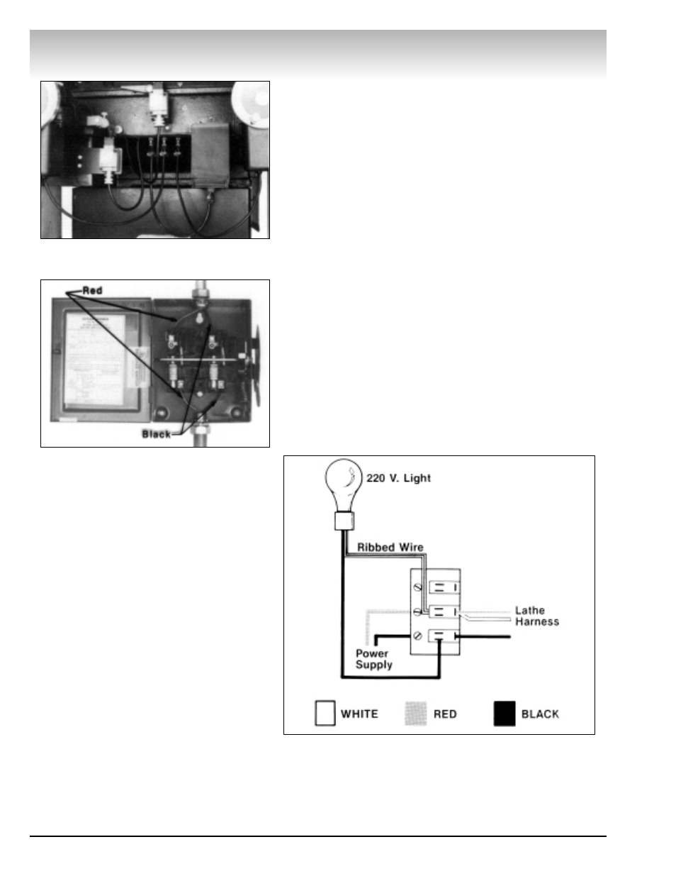
Electrical Hook-Up
Connect one incoming power line to the screw terminal at the
top of the fuse above the red lathe wire and the other power
line to the screw terminal at the top of the fuse above the black
lathe wire, Fig. 2. Check the voltage between the red and black
power lines with a voltmeter. The meter will show 220 volts
when properly wired.
Note: The incoming power lines must be supplied by the con-
sumer and must be in accordance with local code requirements.
The incoming power lines may be colors other than red and
black.
Terminal Block Diagram
Work Lamp
The work lamp is designed for a maximum bulb wattage of 75
watts. Exceeding 75 watts will damage the lamp shade. Be sure
to use 220 volt bulbs only.
Brake Lathes
2 • AMMCO 6000, 6002 Brake Lathes
Figure 1 - Drive Motor Electric Cables Connected To
Terminal Plate
Figure 2 - Disconnect Box Hook-up (Black To Black,
Red To Red)