Brake lathes – AMMCO 6000 Heavy Duty Drum/Disk Lathe User Manual
Page 14
Brake Drum Reconditioning
Although drum turning is usually done on the right side of the
lathe, the left side may also be used by turning the boring bar
upside down in the left hand boring bar clamp.
The following description assumes right hand operation:
1. Measure the diameter of the drum with a brake drum
micrometer. If the drum diameter will be larger than the manu-
facturer’s specified rebore limit after machining, it must be
replaced. Be sure the general condition of the drum is good.
2. Before mounting a hubbed brake drum, inspect the bear-
ings and races for wear. Check a lubricant sample from the bear-
ings for metal particles. An abundance of shiny metal chips
indicate a damaged bearing. Install a new bearing race before
machining the drum. Also, check the hub for a loose race. If the
bearing race can be turned by hand the race recess is worn.
Replace the hub or hub and drum. New bearing races are usu-
ally installed in the hub during manufacturing. Be sure the races
are fully seated in the hub. New bearings should be used with
new races.
3. Mount the drum on the arbor using appropriate adapters,
cones, and spacers. See TYPICAL DRUM MOUNTING illustra-
tions.
4. Wrap a drum silencer band snugly around the drum and
secure it by sliding the buckle finger under the top layer of the
band.
5. Place the boring bar in the boring Bar clamp. Crank the
saddle to its innermost position, then back it out 2 turns.
Position the cross slide so it is close to the open side of the
drum; be sure the drum will not touch the cross slide when the
lathe is turned ON.
6. Position the boring bar and clamp so the inside corner of
the drum can be reached with the tool, and so the boring bar
and clamp will not run into the spindle housing as the cross slide
feeds out. Give the saddle hand wheel one full turn clockwise to
move the tool away from the drum.
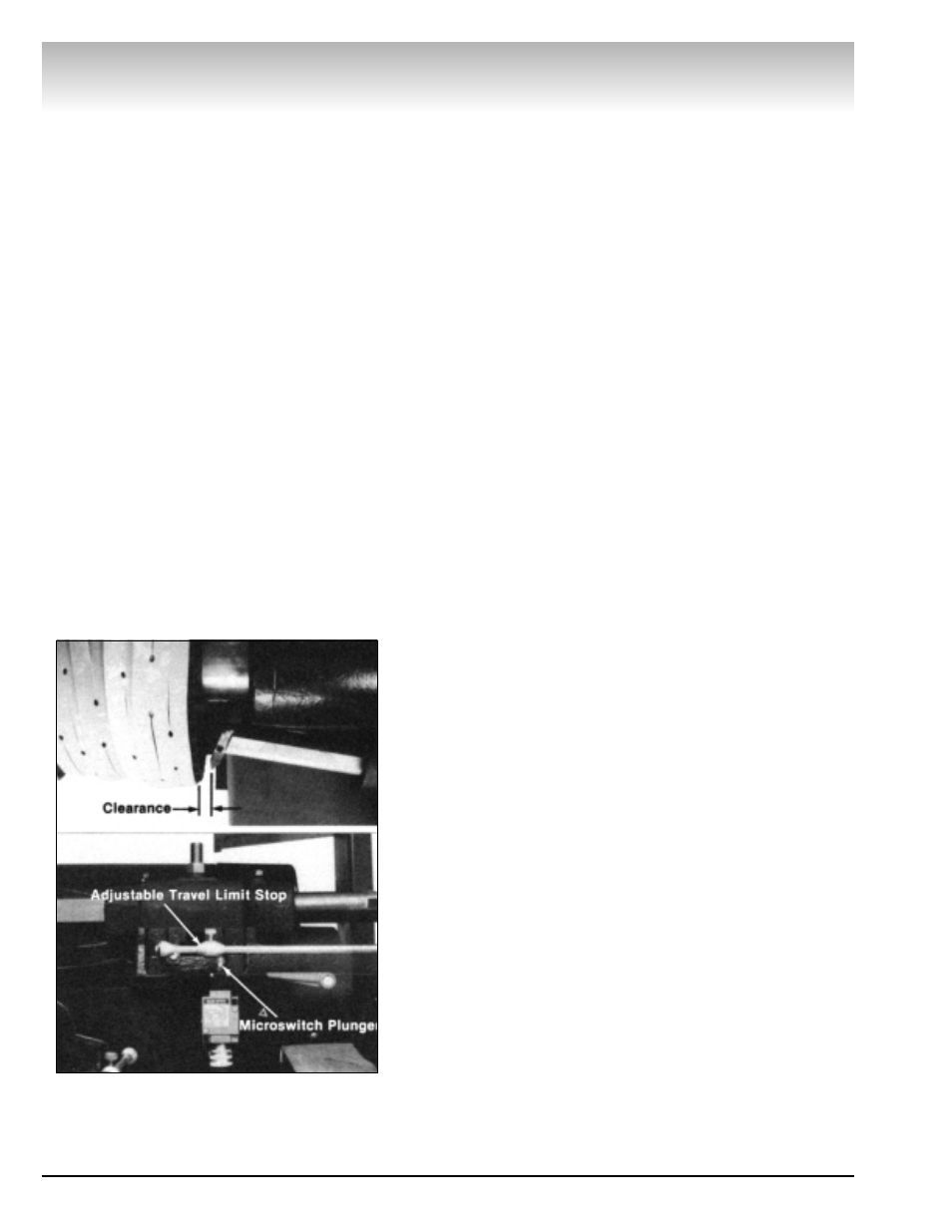
7. Set the cross slide limit switch by either estimating the
travel necessary to cut the full depth of the drum or, if cutting
several drums having the same depth, crank the cross slide
back so the tool bit is 1/4" to 1/2" outside the drum. be sure all
feed gearbox levers are in the DISENGAGE position. TURN THE
LATHE ON. Slide the left adjustable travel limit stop against the
microswitch plunger, Fig. 3. The feed motor will shut off as the
ramp of the adjustable stop depresses the microswitch plunger.
Tighten the lockscrew to hold the stop at this point. Set the right
hand feed direction knob to the DRUM TURN OUT position.
8. Crank the tool bit to the middle of the drum wall. Manually
advance the tool bit until it lightly contacts the drum wall mak-
ing a “scratch” cut.
Brake Lathes
8 • AMMCO 6000, 6002 Brake Lathes
Figure 3 - Setting Limit Switch for Drum Turning