Brake lathes – AMMCO 6000 Heavy Duty Drum/Disk Lathe User Manual
Page 19
adjustable stop depresses the microswitch plunger. Tighten the
lock screw to hold the stop at this point.
9. Advance the tool bits to the approximate center of the rotor
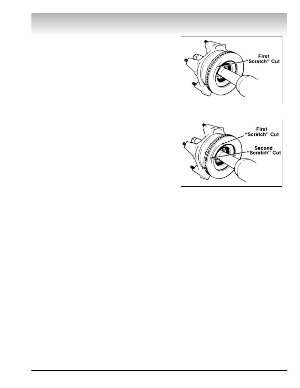
faces. Turn the red and blue depth-of-cut knobs clockwise, one
at a time, until their respective tool bits make light contact with
the rotor face, making a “scratch” cut, Fig. 7.
Note: A “scratch” cut should be no more than .001" deep. If
the “scratch” cut is too deep it will show a continuous line on
the face of the rotor and the runout will not be apparent. Hold
the outer knobs still and turn the inner dials to zero (choose
either inches or millimeters). Back the tool bits away from the
rotor by turning the knobs counterclockwise. Turn the lathe OFF.
10. To check the rotor mounting:
A. Loosen the arbor nut and rotate the rotor one-half turn
(180°) on the adapters.
Note: The adapters must be held to keep them from turning.
Retighten the arbor nut. Back the saddle out one hand wheel
turn and start the lathe. Make a second “scratch” cut on the
outer surface of the rotor only. Turn the lathe OFF.
If the “scratch” cuts are side by side any runout or wobble is
caused by the rotor’s condition.
B. If the “scratch” cuts are opposite each other (180º
apart), the rotor is not properly mounted. Remove the rotor
from the arbor and examine each adapter and the arbor for
nicks, burrs, chips, dirt, and rust. Also inspect the rotor hub
for loose or damaged bearing cups. Clean, repair, remount,
or replace as necessary.
11. Check the settings of the depth-of-cut dials again. Move
the tool bits in until they lightly contact the rotor faces and reset
the dials to zero if necessary.
12. Start the lathe and manually advance the saddle to posi-
tion the outer tool bit at the rotor hub. Set the dial knobs for the
desired depth of cut (inches or millimeters). Set the spindle
speed and set the left hand feed direction knob to the FACE CUT
OUT position. Engage the saddle feed gearbox.
Note: The following spindle speed and feed speed recom-
mendations are intended to serve as a starting point for a
machine operator not familiar with the lathe.
Rotors
Spindle Speed
Feed Speed
Up To 12" Dia.
Fast
Medium Slow
Over 12" Dia.
Medium
Medium Slow
Note: See CONTROL PANEL FUNCTIONS.
Although these settings are relatively slow they should give
the manufacturers recommended finish and good tool life. The
settings shown may be increased considerably; however, tool
life decreases as spindle speed and feed speed are increased.
When the cut is completed, disengage the feed gearbox and
shut the lathe OFF.
Brake Lathes
AMMCO 6000, 6002 Brake Lathes • 13
Figure 7 - Rotor Mounting, First “Scratch” Cut
Figure 8 - Rotor Mounting, Second “Scratch” Cut