JLG 1350SJP Service Manual User Manual
Page 481
SECTION 6 - JLG CONTROL SYSTEM
3121142
– JLG Lift –
6-105
8634
86
34
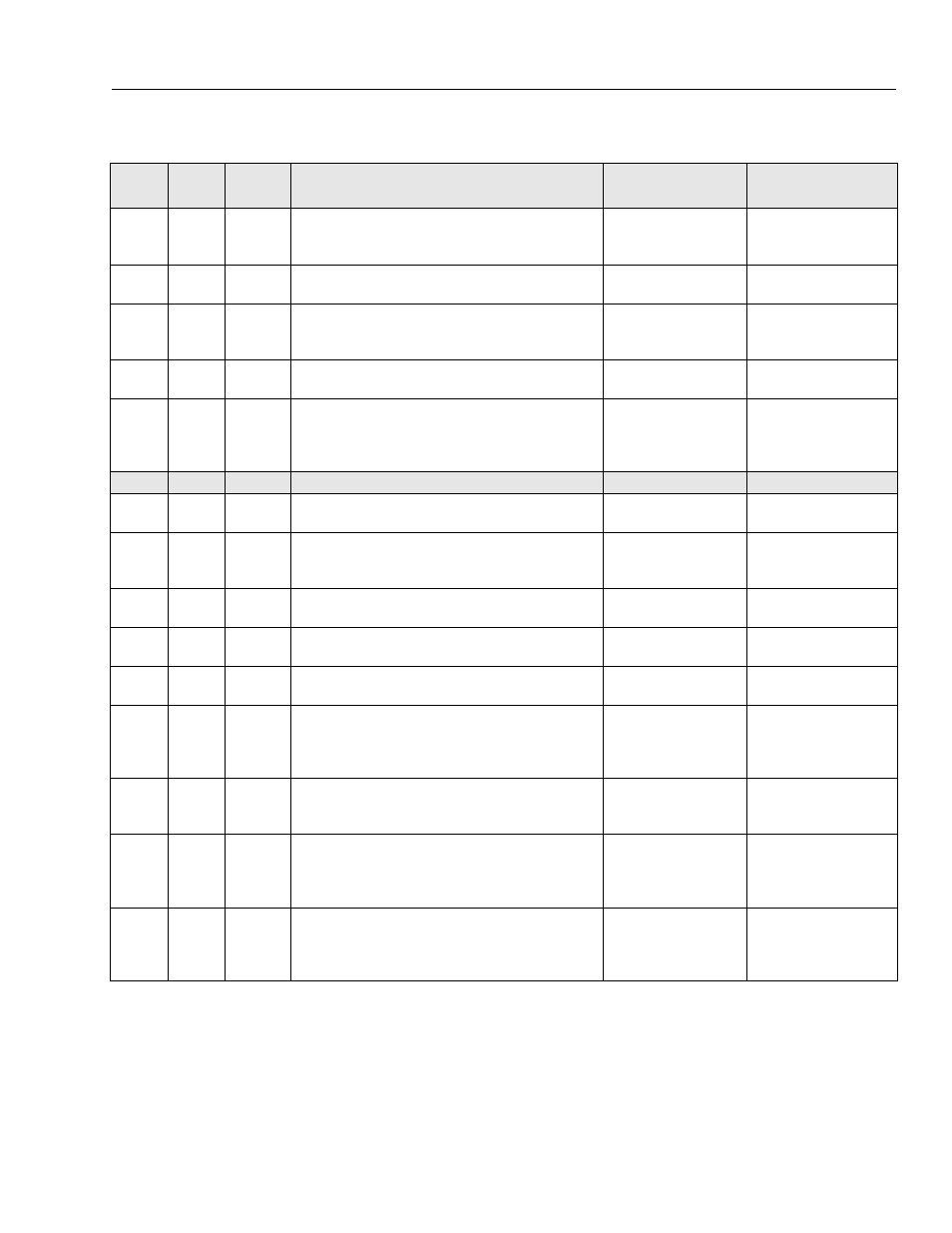
REAR RIGHT STEER SENSOR - SHORT TO GROUND OR OPEN CIRCUIT
There is a Short to Ground or an
Open Circuit to the Rear Right
Steer Sensor.
8635
86
35
REAR RIGHT STEER SENSOR - SHORT TO BATTERY
There is a Short to Battery to the
Rear Right Steer Sensor.
8636
86
36
REAR LEFT STEER SENSOR - SHORT TO GROUND OR OPEN CIRCUIT
There is a Short to Ground or an
Open Circuit to the Rear Left
Steer Sensor.
8637
86
37
REAR LEFT STEER SENSOR - SHORT TO BATTERY
There is a Short to Battery to the
Rear Left Steer Sensor.
8651
86
51
ENGINE SHUTDOWN - AXLE LOCKOUT VALVE FAULT
Engine Start is prevented while
there is an Oscillating Axle fault
and vehicle is out of transport
position
990
99
0
<<< HARDWARE >>>
998
99
8
EEPROM FAILURE - CHECK ALL SETTINGS
The Ground Module has
reported an EEPROM failure.
9910
99
10
FUNCTIONS LOCKED OUT - PLATFORM MODULE SOFTWARE VERSION
IMPROPER
The Platform Module software
version is not compatible with
the rest of the system.
9914
99
14
PLATFORM MODULE SOFTWARE UPDATE REQUIRED
The Platform Module software
requires an updated.
9915
99
15
CHASSIS TILT SENSOR NOT GAIN CALIBRATED
The Chassis Tilt Sensor gain cali-
bration has been lost.
9916
99
16
CHASSIS TILT SENSOR GAIN OUT OF RANGE
The Chassis Tilt Sensor gain cali-
bration has become corrupted.
9917
99
17
HIGH RESOLUTION A2D FAILURE - INTERRUPT LOST
The Platform Module has
reported that its ADS1213 chip
has stopped asserting its inter-
rupt.
9918
99
18
HIGH RESOLUTION A2D FAILURE - REINIT LIMIT
The Platform Module has
reported that its ADS1213 chip
had to be reset 3 or more times.
9919
99
19
GROUND SENSOR REF VOLTAGE OUT OF RANGE
The Ground Module has
reported that its sensor refer-
ence voltage is outside accept-
able range.
- Not reported during power-up.
9920
99
20
PLATFORM SENSOR REF VOLTAGE OUT OF RANGE
The Platform Module has
reported that its sensor refer-
ence voltage is outside accept-
able range.
- Not reported during power-up.
Table 6-6. Diagnostic Trouble Code Chart
DTC
Flash
Code
Sequence
Fault Message
Fault Description
Check