Oss component installation, Oss component installation -31 – JLG 15/20MSP Service Manual User Manual
Page 88
SECTION 4 - CONTROL COMPONENTS
4-32
– JLG Lift –
3121231
OSS Component Installation
THE FOLLOWING ILLUSTRATIONS PROVIDE KEY INSTALLATION
INSTRUCTIONS FOR THE OSS TO OPERATE PROPERLY.
• The OSS Control Module must be electrically isolated
from the mast, see installation instructions below.
• The sensor shield tubes attached to the platform’s
under sides must be properly installed and undamaged
to prevent sensor detection of objects outside the plat-
form parameter.
• The area under the platform floor must be free of any
objects or debris dangling from beneath the platform to
avoid false detection by the sensors.
• DO NOT allow high pressure spray to directly contact
the transducer sensor (circular) membrane, this will
damage the sensor.
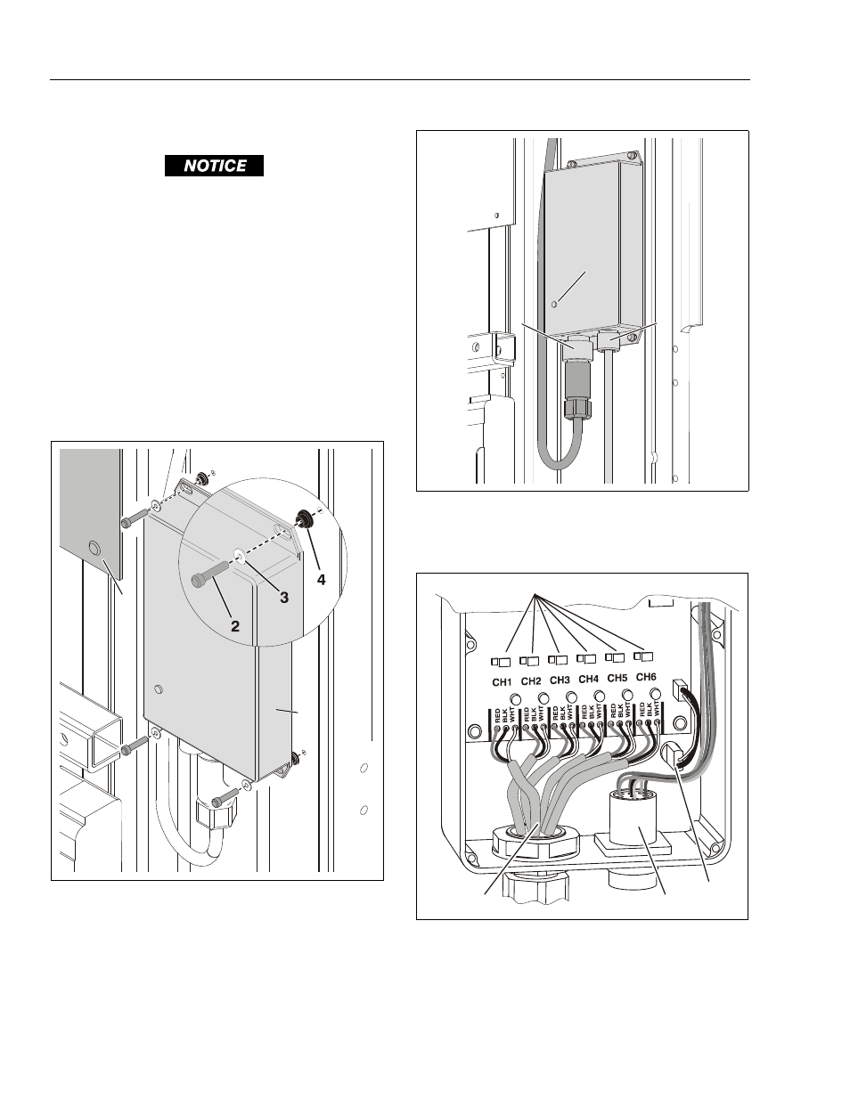
OSS Control Module Installation
1. OSS Control Module
4. Insulating Bushing
2. Mounting Screw (a)
5. Decal Billboard (b)
3. Nylon Washer
Notes:
(a) Apply Loctite 222 to threads.
(b) Drill out pop rivets to remove.
1
5
2
3
4
OSS Control Module Connections
1. RED LED Detection Indicator
3. Junction Box Harness
2. Sensor Harness
Internal View of OSS Control Module (Back Removed)
1. Sensor Comm Channels (a) 3. Wire Harness to Junction Box
2. Sensor Cables
4. LED Indicator Light
Notes:
(a) Channel 1-Sensor 1, Channel 2-Sensor 2, etc.
1
2
3
2
3
4
1